Home /
Expert Answers /
Electrical Engineering /
this-nbsp-load-line-and-q-point-of-the-circuit-in-figure-below-is-shown-in-figure-below-for-the-tra-pa910
(Solved): This load line and Q-point of the circuit in Figure below is shown in Figure below. For the tra ...

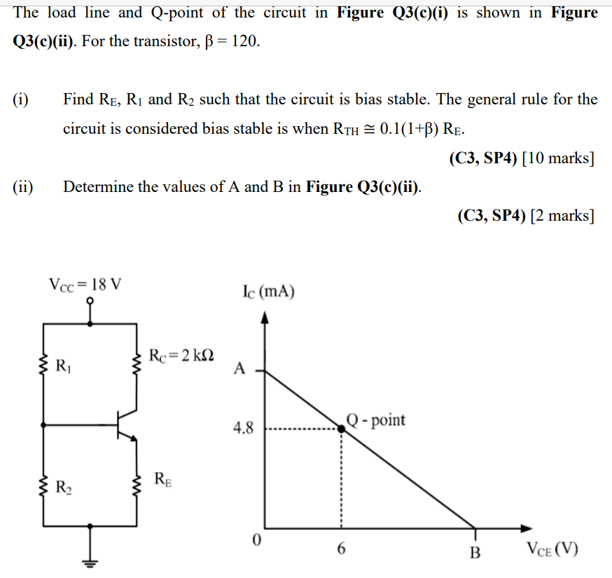
(2) Determine the values of A and B in Figure below
The load line and Q-point of the circuit in Figure Q3(c)(i) is shown in Figure Q3(c)(ii). For the transistor, ß = 120. (i) (ii) ww ww Find RE, R? and R? such that the circuit is bias stable. The general rule for the circuit is considered bias stable is when RTH ? 0.1(1+B) RE. (C3, SP4) [10 marks] Determine the values of A and B in Figure Q3(c)(ii). Vcc= 18 V R? R? Rc = 2 k? RE Ic (mA) A 4.8 0 Q-point 6 (C3, SP4) [2 marks] B VCE (V)