Home /
Expert Answers /
Electrical Engineering /
this-is-a-lab-experiment-help-me-to-complete-this-assigment-with-clear-hand-writing-lab-exerci-pa828
(Solved): This is a Lab Experiment ,help me to complete this assigment with clear hand-writing. Lab Exerci ...
This is a Lab Experiment ,help me to complete this assigment with clear hand-writing.
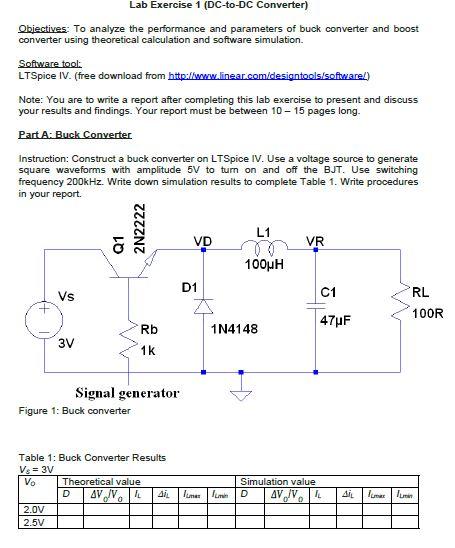
Lab Exercise 1 (DC-to-DC Converter) Objectives: To analyze the performance and parameters of buck converter and boost converter using theoretical calculation and software simulation. Software tool: LTSpice IV. (free download from hitp:iflumw linear.com/designtools/softwarel) Note: You are to write a report after completing this lab exercise to present and discuss your results and findings. Your report must be between \( 10-15 \) pages long. Part A: Buck Converter Instruction: Construct a buck converter on LTSpice IV. Use a voltage source to generate square waveforms with amplitude \( 5 \mathrm{~V} \) to turn on and off the BJT. Use switching frequency \( 200 \mathrm{kHz} \). Write down simulation results to complete Table 1. Write procedures in your report. Table 1: Buck Converter Results \[ V_{e}=3 \mathrm{~V} \]
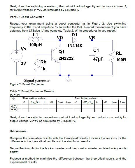
Next, draw the switching waveform, the output load voltage \( V_{o} \) and inductor current \( l_{L} \) for output voltage \( V_{c}=2 \mathrm{~V} \) as simulated by LTSpice IV. Part B: Boost Converter Repeat your experiment using a boost converter as in Figure 2. Use switching frequency \( 200 \mathrm{kHz} \) and amplitude \( 5 \mathrm{~V} \) to switch the BJT. Record measurement you have obtained from LTSpice IV and comblete Table 2. Write procedures in vou recort. Table 2: Boost Converter Results \[ V_{0}=3 \mathrm{~V} \] Next, draw the switching waveform, output load voltage \( V_{o} \) and inductor current \( I_{L} \) for output voltage \( V_{o}=6 V \) as simulated by LTSpice IV. Discussion Compare the simulation results with the theoretical results. Discuss the reasons for the difference in the theoretical results and the simulation results. Derive the formula for the buck converter and the boost converter as listed in Appendix below. Propose a method to minimize the difference between the theoretical results and the experimental results.
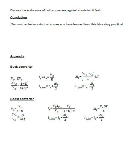
Discuss the endurance of both converters against short-circuit fault. Conclusion Summarize the important outcomes you have leamed from this laboratory practical. Appendix Buck converter \[ \begin{array}{lll} V_{O}=D V_{S} & I_{L}=I_{R}=\frac{V_{O}}{R} & \Delta i_{L}=\left(\frac{V_{S}-V_{O}}{L}\right) D T \\ \frac{\Delta V_{O}}{V_{O}}=\frac{1-D}{B L C f^{2}} & I_{L, \max }=I_{L}+\frac{\Delta i_{L}}{2} & I_{L, \text { mis }}=I_{L}-\frac{\Delta i_{L}}{2} \end{array} \] Boost converter \( V_{o}=\frac{V_{s}}{1-D} \quad I_{L}=\frac{V_{o} I_{o}}{V_{s}}=\frac{V_{S}}{(1-D)^{2} R} \quad \Delta i_{L}=\frac{V_{s} D T}{L} \) \( \frac{\Delta V_{O}}{V_{O}}=\frac{D}{R C f} \quad I_{L, \text { tixa }}=I_{L}+\frac{\Delta i_{L}}{2} \quad I_{L, \text { min }}=I_{L}-\frac{\Delta i_{L}}{2} \)


