Home /
Expert Answers /
Mechanical Engineering /
the-shaft-with-two-helical-gears-attached-shown-in-figure-1-rotates-with-applied-torque-on-gear-a-pa486
(Solved): The shaft with two helical gears attached shown in Figure 1 rotates with applied torque on Gear A. ...

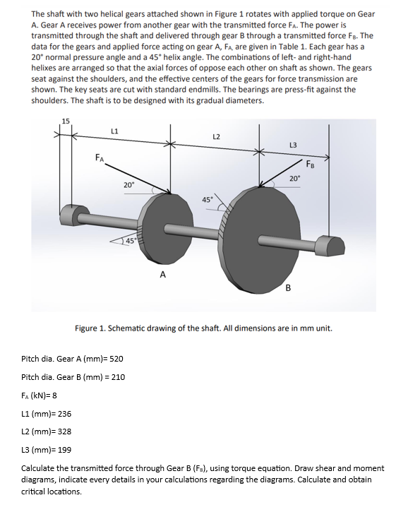
The shaft with two helical gears attached shown in Figure 1 rotates with applied torque on Gear A. Gear A receives power from another gear with the transmitted force . The power is transmitted through the shaft and delivered through gear B through a transmitted force . The data for the gears and applied force acting on gear A, FA, are given in Table 1. Each gear has a normal pressure angle and a helix angle. The combinations of left- and right-hand helixes are arranged so that the axial forces of oppose each other on shaft as shown. The gears seat against the shoulders, and the effective centers of the gears for force transmission are shown. The key seats are cut with standard endmills. The bearings are press-fit against the shoulders. The shaft is to be designed with its gradual diameters. Figure 1. Schematic drawing of the shaft. All dimensions are in mm unit. Pitch dia. Gear Pitch dia. Gear B Calculate the transmitted force through Gear B , using torque equation. Draw shear and moment diagrams, indicate every details in your calculations regarding the diagrams. Calculate and obtain critical locations.