Home /
Expert Answers /
Electrical Engineering /
the-schematic-block-diagram-of-a-heterodyne-front-end-receiver-is-shown-below-pa417
(Solved): The schematic block diagram of a heterodyne front-end receiver is shown below ...

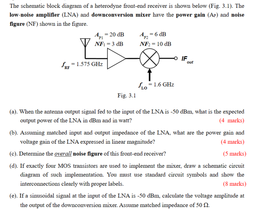
The schematic block diagram of a heterodyne front-end receiver is shown below (Fig. 3.1). The low-noise amplifier (LNA) and downconversion mixer have the power gain (AP) and noise figure (NF) shown in the figure. (a). When the antenna output signal fed to the input of the LNA is \( -50 \mathrm{dBm} \), what is the expected output power of the LNA in \( \mathrm{dBm} \) and in watt? (4 marks) (b). Assuming matched input and output impedance of the LNA, what are the power gain and voltage gain of the LNA expressed in linear magnitude? (4 marks) (c). Determine the overall noise figure of this front-end receiver? (5 marks) (d). If exactly four MOS transistors are used to implement the mixer, draw a schematic circuit diagram of such implementation. You must use standard circuit symbols and show the interconnections clearly with proper labels. (8 marks) (e). If a sinusoidal signal at the input of the LNA is \( -50 \mathrm{dBm} \), calculate the voltage amplitude at the output of the downconversion mixer. Assume matched impedance of \( 50 \Omega \).