Home /
Expert Answers /
Civil Engineering /
the-rigid-pole-and-cross-arm-assembly-is-supported-by-three-cables-as-shown-in-figure-1-a-turn-buc-pa876
(Solved): The rigid pole and cross arm assembly is supported by three cables as shown in Figure 1. A turn buc ...
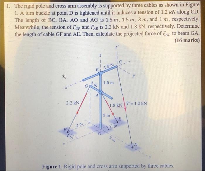
The rigid pole and cross arm assembly is supported by three cables as shown in Figure 1. A turn buckle at point \( \mathrm{D} \) is tightened until it induces a tension of \( 1.2 \mathrm{kN} \) along \( \mathrm{CD} \). The length of \( \mathrm{BC}, \mathrm{BA}, \mathrm{AO} \) and \( \mathrm{AG} \) is \( 1.5 m, 1.5 m, 3 m \), and \( 1 \mathrm{~m} \), respectively. Meanwhile, the tension of \( F_{G F} \) and \( F_{A E} \) is \( 2.2 \mathrm{kN} \) and \( 1.8 \mathrm{kN} \), respectively. Determine the length of cable \( \mathrm{GF} \) and \( \mathrm{AE} \). Then, calculate the projected force of \( F_{G F} \) to beam \( \mathrm{GA} \). (16 marks)
Expert Answer
length of cable GF, lGF=22+32=3.61m length of cable AE, lAE=1.52+32=3.35m