(Solved): The reinforced concrete beam shown in Figure 1 is designed tocarry vertically uniformly distributed ...
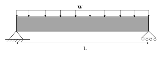
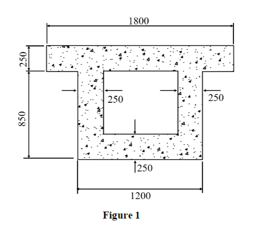
The reinforced concrete beam shown in Figure 1 is designed to carry vertically uniformly distributed loads (w). The dead load G is 70 kN/m, self-weight included. The live load Q is 90 kN/m. The beam span L is 15 m. The effective depth d is 1030mm and the effective width bef is 1800 mm. The reinforcement is composed of normal class N steel bars (Es = 200000 MPa; fsy = 500 MPa). The characteristic compressive strength of concrete is 40 MPa. The exposure condition of the beam is A1. This beam is domestic structure that located in Tarcoola.
1. Calculate the design bending moment M*u for the maximum loads.
2. Design tensile steel Ast and select the appropriate reinforcing bars.
3. Check total deflection (short + long terms) and compare with AS 3600 Service Limit State.
(Please use clause 8.5.3.1 and Equation 8.5.3.1(1). Note: The effect of concrete shrinkage will be included in long term deflection only.)
4. Design the stirrups required according to AS 3600:2018.
PLEASE MAKE SURE ALL QUESTIONS ARE ANSWERED AND THE CORRECT VALUES ARE USED FROM THE QUESTION!