Home /
Expert Answers /
Electrical Engineering /
the-rc-circuit-shown-in-figure-1-can-be-used-in-an-artificial-pacemaker-to-establish-a-normal-hear-pa428
(Solved): The RC circuit shown in (Figure 1) can be used in an artificial pacemaker to establish a normal hear ...
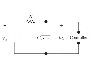
The RC circuit shown in (Figure 1) can be used in an artificial pacemaker to establish a normal heart rhythm by generating periodic electrical impulses. The box labeled "controller" behaves as an open circuit until the voltage drop across the capacitor reaches a preset limit. Once that limit is reached, the capacitor discharges its stored energy in the form of an electrical impulse to the heart, starts to recharge, and then the process repeats.

PART A:
Calculate the heart rate in beats per minute for R = 140 k? and C = 4.0 ?F, if the capacitor discharges when its voltage reaches 80% of the source voltage Vs.
Express your answer in beats per minute to three significant figures.
Expert Answer
To ascertain the heart rate in beats per minute, we first need to decide the time it takes for the capacitor to energize to 80% of the source voltage (Versus) We can involve the recipe for the voltage across the capacitor as a component of time during the charging system:Vc(t) = Versus * (1 - e^(- t/?))where Vc(t) is the voltage across the capacitor at time t, Versus is the source voltage, ? is the time constant (RC), and e is the foundation of the natural logarithm (roughly 2.718).