Home /
Expert Answers /
Electrical Engineering /
the-one-line-diagram-of-a-three-phase-power-system-is-shown-below-select-a-common-base-of-100-mva-pa985
(Solved): The one-line diagram of a three-phase power system is shown below. Select a common base of 100 MVA ...
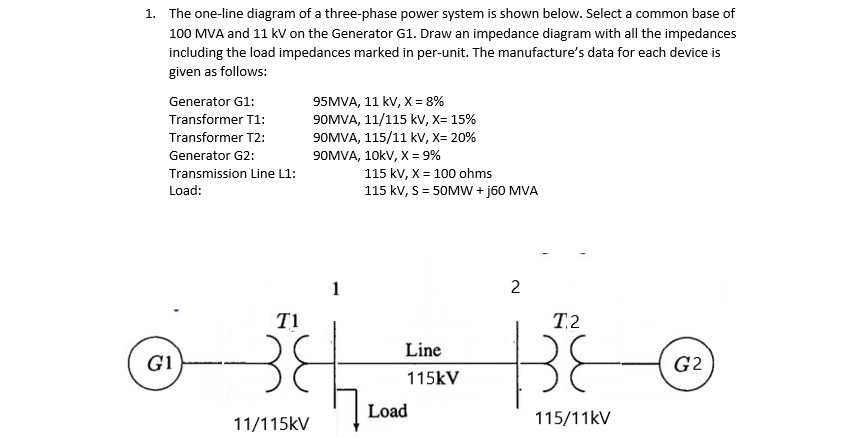
The one-line diagram of a three-phase power system is shown below. Select a common base of 100 MVA and \( 11 \mathrm{kV} \) on the Generator G1. Draw an impedance diagram with all the impedances including the load impedances marked in per-unit. The manufacture's data for each device is given as follows: Generator G1: \( \quad 95 \mathrm{MVA}, 11 \mathrm{kV}, \mathrm{X}=8 \% \) Transformer T1: \( \quad \) 90MVA \( , 11 / 115 \mathrm{kV}, \mathrm{X}=15 \% \) Transformer T2: \( \quad \) 90MVA \( , 115 / 11 \mathrm{kV}, \mathrm{X}=20 \% \) Generator G2: \( \quad \) 90MVA, \( 10 \mathrm{kV}, \mathrm{X}=9 \% \) Transmission Line L1: \( \quad 115 \mathrm{kV}, \mathrm{X}=100 \mathrm{ohms} \) Load: \( \quad 115 \mathrm{kV}, \mathrm{S}=50 \mathrm{MW}+\mathrm{j} 60 \mathrm{MVA} \)
