Home /
Expert Answers /
Electrical Engineering /
the-inductor-and-capacitor-in-the-diagram-below-are-part-of-the-output-coupling-network-of-a-radio-pa381
(Solved): The inductor and capacitor in the diagram below are part of the output-coupling network of a radio ...
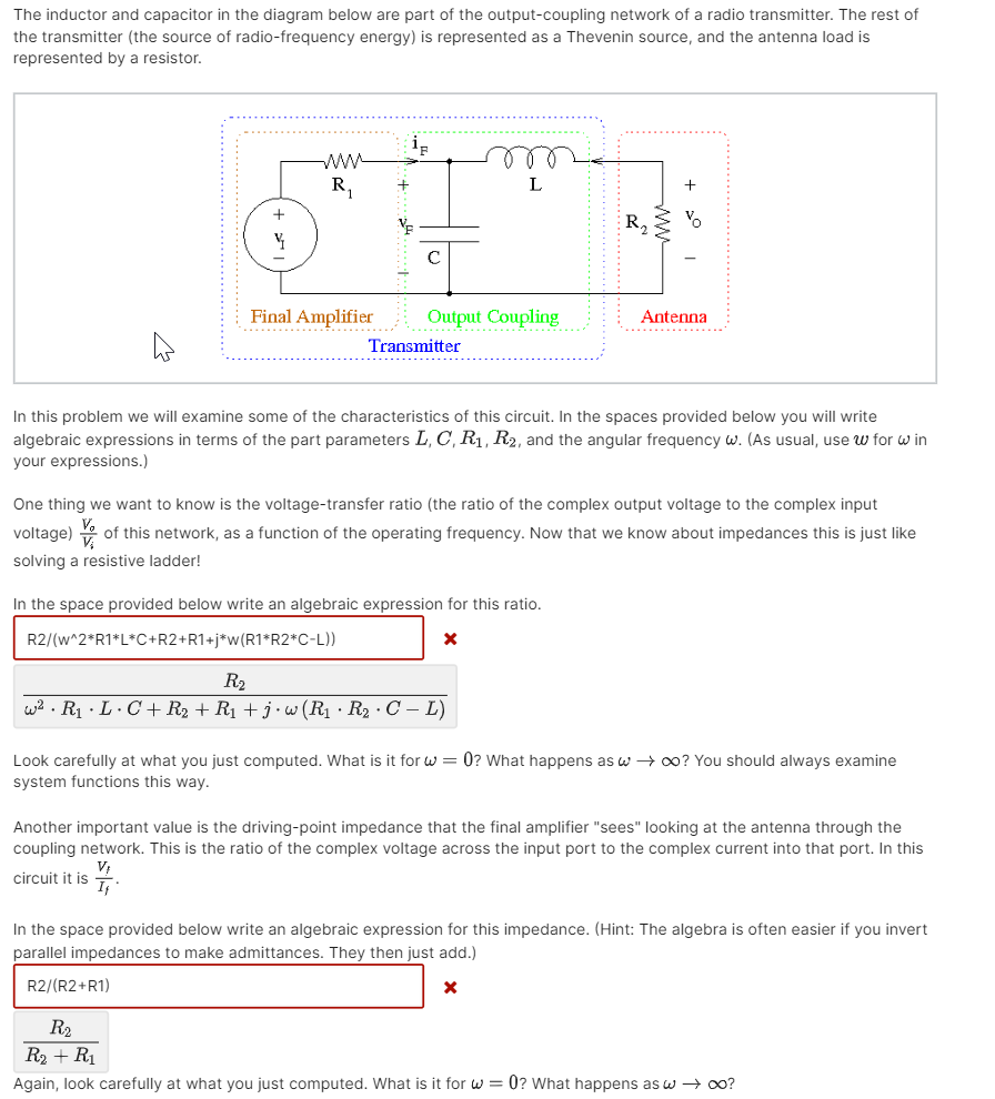
The inductor and capacitor in the diagram below are part of the output-coupling network of a radio transmitter. The rest of the transmitter (the source of radio-frequency energy) is represented as a Thevenin source, and the antenna load is represented by a resistor. ip ww r R? + L + VF Final Amplifier Antenna Output Coupling Transmitter In this problem we will examine some of the characteristics of this circuit. In the spaces provided below you will write algebraic expressions in terms of the part parameters L, C, R?, R?, and the angular frequency w. (As usual, use w for win your expressions.) One thing we want to know is the voltage-transfer ratio (the ratio of the complex output voltage to the complex input voltage) of this network, as a function of the operating frequency. Now that we know about impedances this is just like solving a resistive ladder! In the space provided below write an algebraic expression for this ratio. R2/(w^2*R1*L*C+R2+R1+j*w (R1*R2*C-L)) X R? w²R?.L.C + R? + R? + j·w (R? R? · C - L) Look carefully at what you just computed. What is it for w=0? What happens as w??? You should always examine system functions this way. Another important value is the driving-point impedance that the final amplifier "sees" looking at the antenna through the coupling network. This is the ratio of the complex voltage across the input port to the complex current into that port. In this V? circuit it is If In the space provided below write an algebraic expression for this impedance. (Hint: The algebra is often easier if you invert parallel impedances to make admittances. They then just add.) R2/(R2+R1) X R? R? + R? Again, look carefully at what you just computed. What is it for w=0? What happens as w ? ?0?
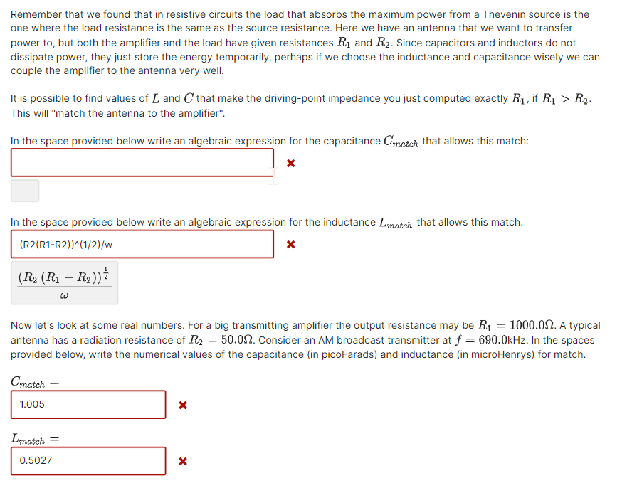
Remember that we found that in resistive circuits the load that absorbs the maximum power from a Thevenin source is the one where the load resistance is the same as the source resistance. Here we have an antenna that we want to transfer power to, but both the amplifier and the load have given resistances R? and R?. Since capacitors and inductors do not dissipate power, they just store the energy temporarily, perhaps if we choose the inductance and capacitance wisely we can couple the amplifier to the antenna very well. It is possible to find values of L and C that make the driving-point impedance you just computed exactly R?, if R? > R?. This will "match the antenna to the amplifier". In the space provided below write an algebraic expression for the capacitance Cmatch that allows this match: x In the space provided below write an algebraic expression for the inductance Imatch that allows this match: (R2(R1-R2))^(1/2)/w (R? (R? - R?)) W Now let's look at some real numbers. For a big transmitting amplifier the output resistance may be R? = 1000.00. A typical antenna has a radiation resistance of R? = 50.00. Consider an AM broadcast transmitter at f= 690.0kHz. In the spaces provided below, write the numerical values of the capacitance (in picoFarads) and inductance (in microHenrys) for match. Cmatch = 1.005 X Lmatch X 0.5027 X