Home /
Expert Answers /
Computer Science /
the-following-plc-connection-diagram-explains-the-drilling-operation-with-delay-modify-the-circui-pa953
(Solved): The following PLC connection diagram explains the drilling operation with delay. Modify the circui ...
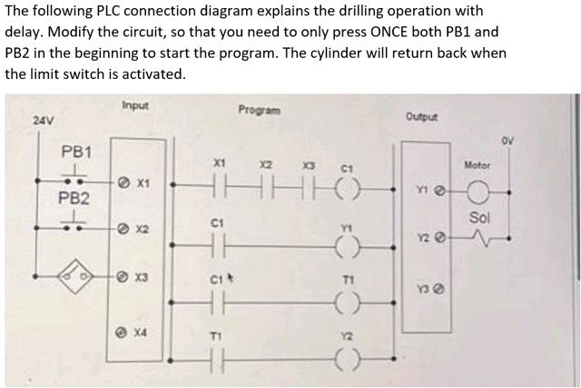
The following PLC connection diagram explains the drilling operation with delay. Modify the circuit, so that you need to only press ONCE both PB1 and PB2 in the beginning to start the program. The cylinder will return back when the limit switch is activated.
Expert Answer
To change the circuit so that a single press of PB1 and PB2 starts the program, remove the latch circuits (two AND and OR gates) connected to PB1 and