Home /
Expert Answers /
Mechanical Engineering /
the-figure-bellow-presents-the-circuit-diagram-of-a-speed-control-system-in-which-the-dc-motor-vol-pa724
(Solved): The figure bellow presents the circuit diagram of a speed-control system in which the dc motor vol ...
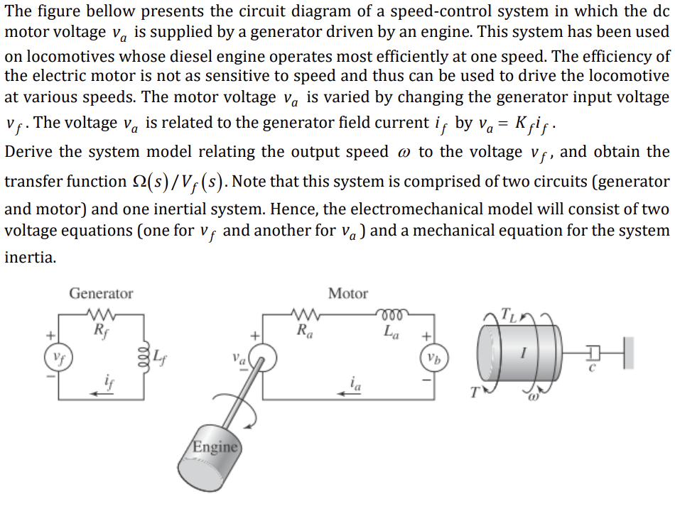
The figure bellow presents the circuit diagram of a speed-control system in which the dc motor voltage vå is supplied by a generator driven by an engine. This system has been used on locomotives whose diesel engine operates most efficiently at one speed. The efficiency of the electric motor is not as sensitive to speed and thus can be used to drive the locomotive at various speeds. The motor voltage vais varied by changing the generator input voltage Vf. The voltage va is related to the generator field current iƒ by v? = Kƒiƒ . Derive the system model relating the output speed @ to the voltage vƒ, and obtain the transfer function ?(s)/Vƒ (s). Note that this system is comprised of two circuits (generator and motor) and one inertial system. Hence, the electromechanical model will consist of two voltage equations (one for vƒ and another for vå) and a mechanical equation for the system inertia. Vf Generator www Rf 000 Engine) www Ra Motor ia voo La + Vb T H
