Home /
Expert Answers /
Mechanical Engineering /
the-700-mathrm-mm-pipe-shown-in-figure-1-conducts-water-from-reservoir-a-to-a-pressure-tur-pa325
(Solved): The \( 700-\mathrm{mm} \) pipe shown in Figure 1 conducts water from reservoir A to a pressure tur ...
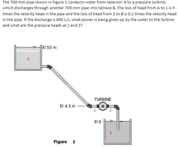
The \( 700-\mathrm{mm} \) pipe shown in Figure 1 conducts water from reservoir A to a pressure turbine, which discharges through another \( 700-\mathrm{mm} \) pipe into tailrace B. The loss of head from A to 1 is 5 times the velocity head in the pipe and the loss of head from 2 to \( \mathrm{B} \) is \( 0.2 \) times the velocity head in the pipe. If the discharge is \( 600 \mathrm{~L} / \mathrm{s} \), what power is being given up by the water to the turbine and what are the pressure heads at 1 and 2 ?
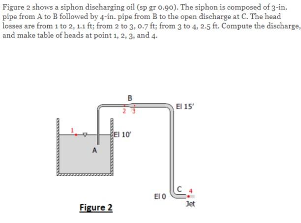
Figure 2 shows a siphon discharging oil (sp gr \( 0.90 \) ). The siphon is composed of 3 -in. pipe from \( A \) to \( B \) followed by 4 -in. pipe from \( B \) to the open discharge at \( C \). The head losses are from 1 to \( 2,1.1 \mathrm{ft} \); from 2 to \( 3,0.7 \mathrm{ft} \); from 3 to \( 4,2.5 \mathrm{ft} \). Compute the discharge, and make table of heads at point \( 1,2,3 \), and 4 .