Home /
Expert Answers /
Electrical Engineering /
step-by-steps-and-what-components-use-pspice-simulate-a-bicmos-inverter-to-obtain-1-the-vtc-curve-pa863
(Solved): step by steps and what components Use PSPICE. Simulate a BiCMOS inverter to obtain 1. The VTC curve ...
step by steps and what components
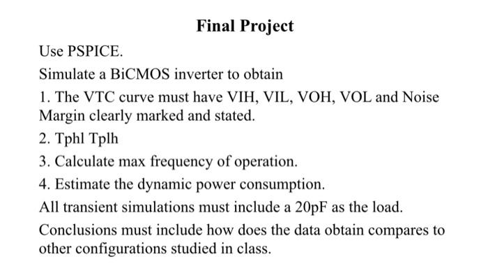
Use PSPICE. Simulate a BiCMOS inverter to obtain 1. The VTC curve must have VIH, VIL, VOH, VOL and Noise Margin clearly marked and stated. 2. Tphl Tplh 3. Calculate max frequency of operation. 4. Estimate the dynamic power consumption. All transient simulations must include a as the load. Conclusions must include how does the data obtain compares to other configurations studied in class.
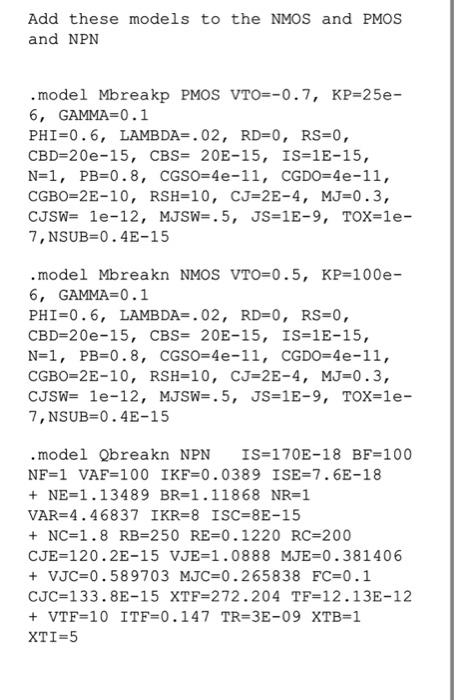
Add these models to the NMOS and PMOS and NPN . model Mbreakp PMOS VTO=-0.7, KP=25e6, , , , , , , 7, NSUB . model Mbreakn NMOS VTO 6, , , , IS , , , . model Qbreakn NPN IS IKR ISC