Home /
Expert Answers /
Electrical Engineering /
slow-counter-verilog-design-and-implement-a-circuit-that-successively-flashes-digits-0-through-9-on-pa415
(Solved): slow counter verilog Design and implement a circuit that successively flashes digits 0 through 9 on ...

slow counter
verilog
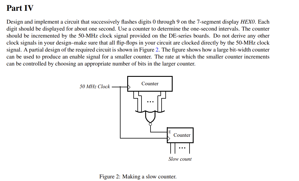
Design and implement a circuit that successively flashes digits 0 through 9 on the 7-segment display HEXO. Each digit should be displayed for about one second. Use a counter to determine the one-second intervals. The counter should be incremented by the clock signal provided on the DE-series boards. Do not derive any other clock signals in your design-make sure that all flip-flops in your circuit are clocked directly by the clock signal. A partial design of the required circuit is shown in Figure 2. The figure shows how a large bit-width counter can be used to produce an enable signal for a smaller counter. The rate at which the smaller counter increments can be controlled by choosing an appropriate number of bits in the larger counter. Figure 2: Making a slow counter.
Expert Answer
As it is mentioned in the question itself, we will be making two counters to achieve our goal. First counter will help us get the one second interval and other counter will will be a mod 10 counter that will count from 0-9 continuously. ------------------------------------------------------------------------------------------------------------------------------------------------------ First we should discuss how a counter works. We will use T flip flops for the same. -10 counter that will count from 0-9 continuously. ------------------------------------------------------------------------------------------------------------------------------------------------------ First we should discuss how a counter works. We will use T flip flops for the same.The flip flops are negative edge triggered. Negative edge triggered means that when the clock pulse wil go from a value of 1 to a value of 0, then the toggle is triggered. The flip flop A0 is connected to the clock signal. and the T of both flip flops are connected to logic 1. Initially the outut on both Q is 0. Initially, both output of A0 [Q0] is set to 0 and output if A1 [Q1] is set to 0. So, our value of Q1 = 0 , Q0 = 0 [i.e. 0] When the clock pulses for the first time, Output Q of A0 toggles from 0 to 1. SInce it is a rising edge, A1 is not triggered. So, our value of Q1 = 0 , Q0 = 1. [i.e 1] When the clock pulses again, Q0 toggles and goes from 1 to 0. Since it is the falling edge now, A1 is triggered and Q1 toggles. So, now our value of Q1 = 1, Q0 = 0. [i.e. 2] When the clock pulses again, Q0 toggles from 0 to 1, and since it is a rising edge this time, A1 is not triggered. So, our value of Q1 = 1, Q0 = 1. [i.e. 3] When the clock pulses this time, Q0 toggles from 1 to 0, and since it is a falling edge, A1 is also triggered, and Q1 toggles fro 1 to 0. So, our new values are, Q1 = 0, Q0 = 0. [i.e. 0]