Home /
Expert Answers /
Mechanical Engineering /
shaft-design-under-static-loading-consider-the-shaft-shown-below-the-loads-on-gears-b-and-c-are-a-pa490
(Solved): Shaft Design under Static Loading: Consider the shaft shown below. The loads on gears B and C are a ...
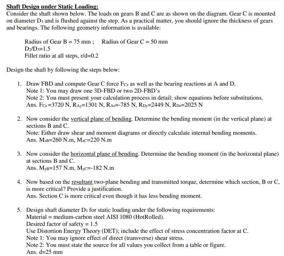
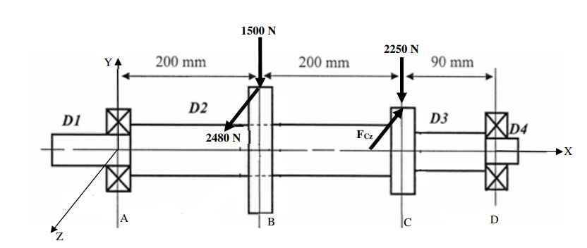
Shaft Design under Static Loading: Consider the shaft shown below. The loads on gears B and C are as shown on the diagram. Gear C is mounted on diameter and is flushed against the step. As a practical matter, you should ignore the thickness of gears and bearings. The following geometry information is available: Design the shaft by following the steps below: 1. Draw and compute Gear force as well as the bearing reactions at and . Note 1: You may draw one 3D-FBD or two 2D-FBD's Note 2: You must present your calculation process in detail; show equations before substitutions. Ans. 2. Now consider the vertical plane of bending. Determine the bending moment (in the vertical plane) at sections B and C. Note: Either draw shear and moment diagrams or directly calculate internal bending moments. Ans. 3. Now consider the horizontal plane of bending. Determine the bending moment (in the horizontal plane) at sections and . Ans. 4. Now based on the resultant two-plane bending and transmitted torque, determine which section, B or C, is more critical? Provide a justification. Ans. Section is more critical even though it has less bending moment. 5. Design shaft diameter for static loading under the following requirements: Material medium-carbon steel AISI 1080 (HotRolled). Desired factor of safety Use Distortion Energy Theory (DET); include the effect of stress concentration factor at C. Note 1: You may ignore effect of direct (transverse) shear stress. Note 2: You must state the source for all values you collect from a table or figure. Ans.

