Home /
Expert Answers /
Civil Engineering /
seepage-exists-in-the-soil-profile-in-figure-a-thickness-of-the-dry-sand-and-saturated-sand-layers-pa777
(Solved): Seepage exists in the soil profile in Figure a. Thickness of the dry sand and saturated sand layers ...
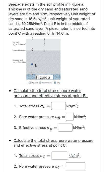
Seepage exists in the soil profile in Figure a. Thickness of the dry sand and saturated sand layers are \( 5 \mathrm{~m} \) and \( 12 \mathrm{~m} \), respectively.Unit weight of dry sand is \( 16.5 \mathrm{kN} / \mathrm{m}^{3} \), unit weight of saturated sand is \( 19.25 \mathrm{kN} / \mathrm{m}^{3} \). Point \( \mathrm{E} \) is in the middle of saturated sand layer. A piezometer is inserted into point \( \mathrm{C} \) with a reading of \( \mathrm{h}=14.6 \mathrm{~m} \). - Calculate the total stress, pore water pressure and effective stress at point B. 1. Total stress \( \sigma_{B}=\quad \mathrm{kN} / \mathrm{m}^{2} \); 2. Pore water pressure \( u_{B}=\quad \mathrm{kN} / \mathrm{m}^{2} \); 3. Effective stress \( \sigma_{B}^{\prime}=\quad \mathrm{kN} / \mathrm{m}^{2} \); - Calculate the total stress, pore water pressure and effective stress at point \( C \). 1. Total stress \( \sigma_{C}=\quad \underline{\mathrm{kN} / \mathrm{m}^{2}} \); 2. Pore water pressure \( u_{C}= \)
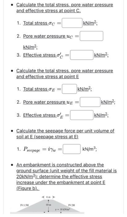
- Calculate the total stress, pore water pressure and effective stress at point \( C \). 1. Total stress \( \sigma_{C}=\quad \underline{\mathrm{kN} / \mathrm{m}^{2}} \); 2. Pore water pressure \( u_{C}= \) \( \mathrm{kN} / \mathrm{m}^{2} \); 3. Effective stress \( \sigma_{C}^{\prime}=\quad \quad \mathrm{kN} / \mathrm{m}^{2} \); - Calculate the total stress, pore water pressure and effective stress at point \( E \) 1. Total stress \( \sigma_{E}=\quad \underline{\mathrm{kN} / \mathrm{m}^{2}} \); 2. Pore water pressure \( u_{E}=\quad \mathrm{kN} / \mathrm{m}^{2} \); 3. Effective stress \( \sigma_{E}^{\prime}=\quad \quad \mathrm{kN} / \mathrm{m}^{2} \); - Calculate the seepage force per unit volume of soil at \( E \) (seepage stress at \( E \) ). 1. \( P_{\text {seepage }}=i \gamma_{w}=\quad \mathrm{kN} / \mathrm{m}^{3} \); - An embankment is constructed above the ground surface (unit weight of the fill material is \( 20 \mathrm{kN} / \mathrm{m}^{3} \) ); determine the effective stress increase under the embankment at point \( E \) (Figure b).
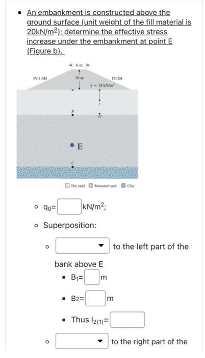
- An embankment is constructed above the ground surface (unit weight of the fill material is \( 20 \mathrm{kN} / \mathrm{m}^{3} \) ); determine the effective stress increase under the embankment at point \( E \) (Figure b).
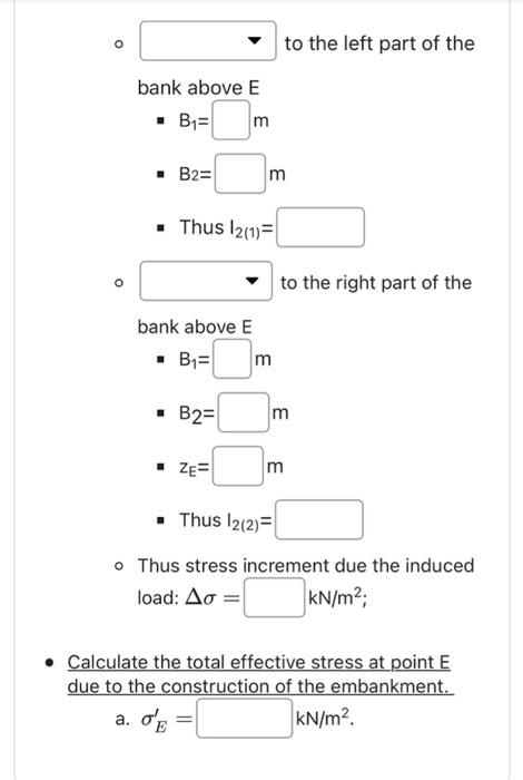
- to the left part of the bank above \( \mathrm{E} \) - \( B_{1}=m \) - \( B_{2}=m \) - Thus \( I_{2(1)}= \) \( - \) to the right part of the bank above \( E \) - \( B_{1}=m \) - \( B_{2}=m \) - \( z_{E}=m \) - Thus \( \mathrm{I}_{2(2)}= \) - Thus stress increment due the induced load: \( \Delta \sigma=\quad \mathrm{kN} / \mathrm{m}^{2} \); - Calculate the total effective stress at point \( E \) due to the construction of the embankment. a. \( \sigma_{E}^{\prime}= \) \( \mathrm{kN} / \mathrm{m}^{2} \).
Expert Answer
5m12m6mCEBA ?dry=16.5KNm3 ?sat=19.25KNm314.5m At point B total stress, ?B=16.5×5kNm2=82.5KNm2 pare water pressure, effective stress, uB=0?B1=?B?UB=82.