Home /
Expert Answers /
Electrical Engineering /
question-derive-the-closed-loop-transfer-function-figure-q2-shows-a-closed-loop-anti-vibration-con-pa201
(Solved): Question : Derive the closed loop transfer function Figure Q2 shows a closed loop anti-vibration con ...
Question : Derive the closed loop transfer function
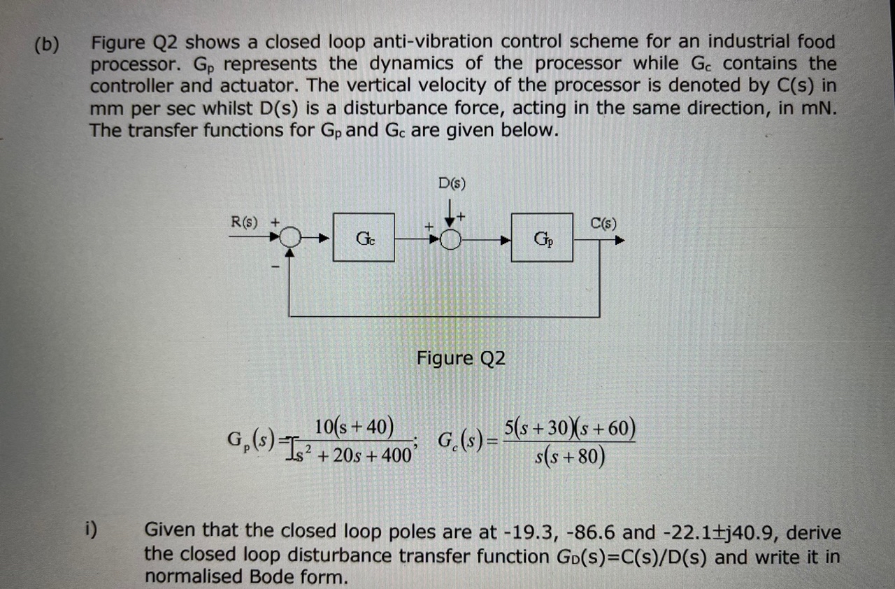
Figure Q2 shows a closed loop anti-vibration control scheme for an industrial food processor. \\( G_{p} \\) represents the dynamics of the processor while \\( G_{c} \\) contains the controller and actuator. The vertical velocity of the processor is denoted by \\( \\mathrm{C}(\\mathrm{s}) \\) in \\( \\mathrm{mm} \\) per sec whilst \\( \\mathrm{D}(\\mathrm{s}) \\) is a disturbance force, acting in the same direction, in \\( \\mathrm{mN} \\). The transfer functions for \\( \\mathrm{G}_{\\mathrm{p}} \\) and \\( \\mathrm{G}_{\\mathrm{c}} \\) are given below. Figure Q2 \\[ G_{p}(s)=\\int_{s^{2}+20 s+400} ; \\quad G_{c}(s)=\\frac{5(s+30)(s+60)}{s(s+80)} \\] i) Given that the closed loop poles are at \\( -19.3,-86.6 \\) and \\( -22.1 \\pm j 40.9 \\), derive the closed loop disturbance transfer function \\( G_{D}(s)=C(s) / D(s) \\) and write it in normalised Bode form.