Home /
Expert Answers /
Electrical Engineering /
question-2-34-the-diagram-below-illustrates-a-bridge-rectifier-circuit-connected-to-an-ideal-transfo-pa720
(Solved): Question 2 \"The diagram below illustrates a bridge rectifier circuit connected to an ideal transfo ...
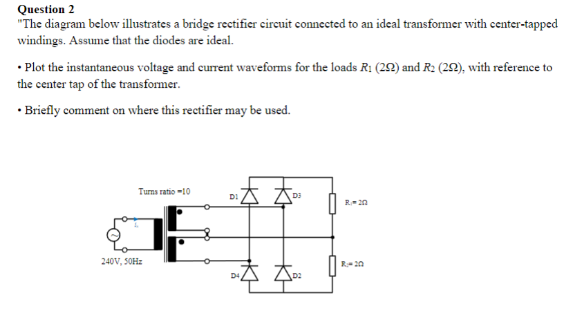
Question 2 \"The diagram below illustrates a bridge rectifier circuit connected to an ideal transformer with center-tapped windings. Assume that the diodes are ideal. - Plot the instantaneous voltage and current waveforms for the loads \\( R_{1}(2 \\Omega) \\) and \\( R_{2}(2 \\Omega) \\), with reference to the center tap of the transformer. - Briefly comment on where this rectifier may be used.