Home /
Expert Answers /
Mechanical Engineering /
q21-the-figure-showing-below-is-the-simulink-input-output-blocks-the-simulink-model-uses-signal-pa960
(Solved): Q21 - The figure showing below is the Simulink input/output blocks, the Simulink model uses signal ...
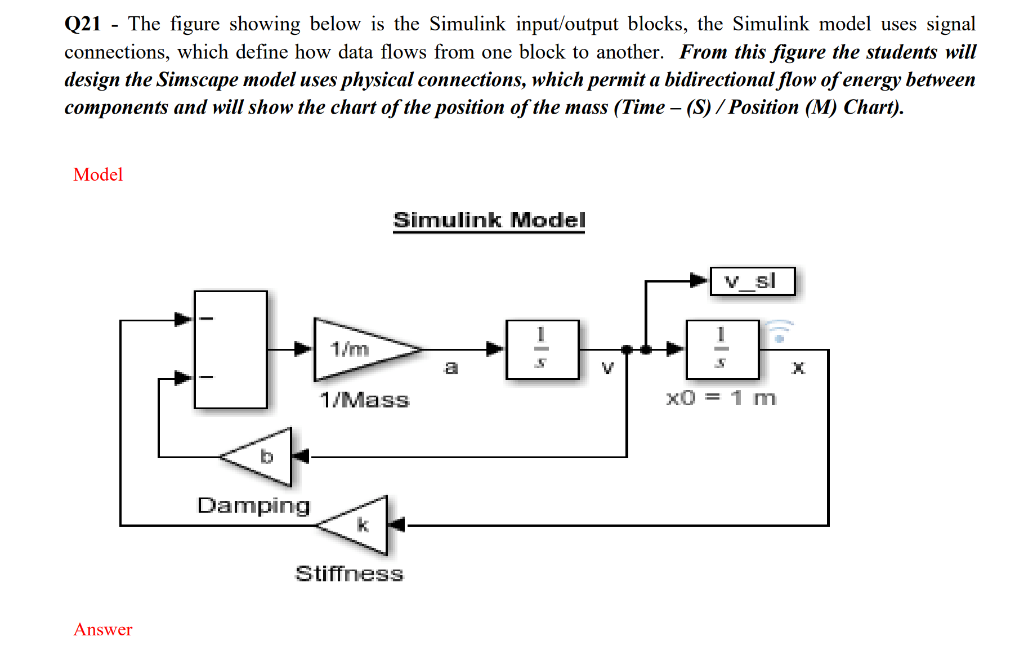
Q21 - The figure showing below is the Simulink input/output blocks, the Simulink model uses signal connections, which define how data flows from one block to another. From this figure the students will design the Simscape model uses physical connections, which permit a bidirectional flow of energy between components and will show the chart of the position of the mass (Time - (S) / Position (M) Chart). Mnde1 Answer
Expert Answer
please see the above explanation