Home /
Expert Answers /
Operations Management /
q1-case-study-read-the-following-case-study-in-your-textbook-case-study-4-2-process-improvemen-pa676
(Solved): Q1 - Case Study Read the following case study in your textbook: Case Study 4.2: Process improvemen ...
Q1
- Case Study Read the following case study in your textbook: Case Study 4.2: Process improvement Complete Parts 1-4 of the case. In addition to completine, the four parts of the case study, consider at least one additional method for identifying the underlying issue causing the observed problem that is not listed in the case, and briefly describe how you would employ it.
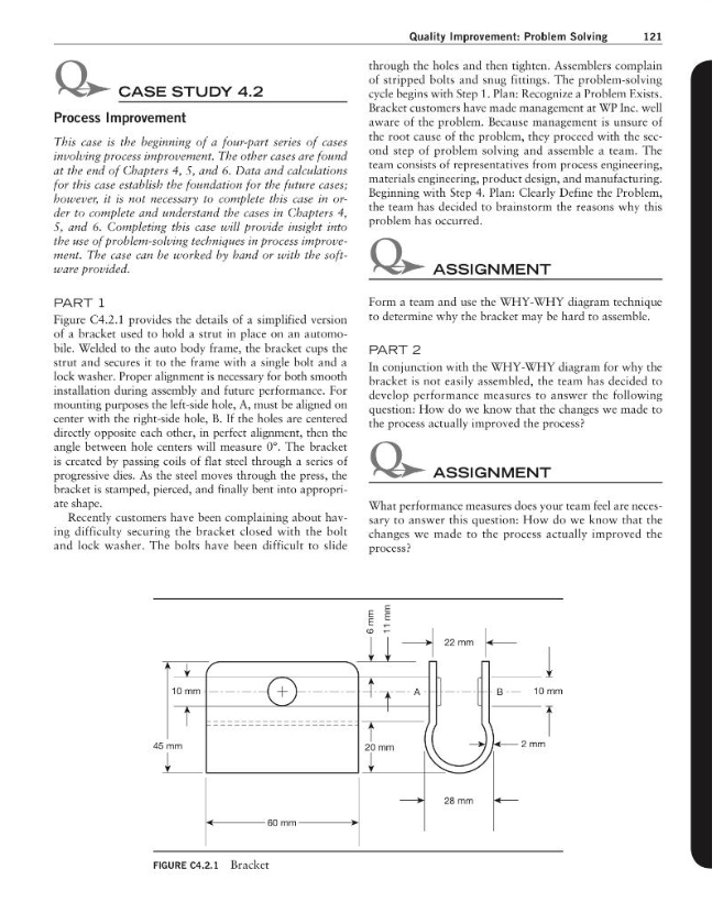
Quality Improvement: Problem Solving 121 CASE STUDY 4.2 Process Improvement This case is the beginning of a four-part series of cases involuing process improwensen. The other cases are found at the end of Chapters 4, 5, and 6. Data and calculations for this case establish the foundation for the future cases; bowever, it is not necessary to complete this case in order to complete and understand the cases in Chapters 4, 5, and 6. Completing this case will provide insight into the use of problem-solving technigues in process improve. ment. The case can be worked by band or with the software provided. PART 1 Figure C4.2.1 provides the details of a simplified version of a bracket used to hold a strut in place on an automobile. Welded to the auto body frame, the bracket cups the strut and secures it to the frame with a single bolt and a lock washer. Proper alignment is necessary for both smooth installation during assembly and future performance. For mounting purposes the left-side hole, , must be aligned on center with the right-side hole, B. If the holes are centered directly opposite each other, in perfect alignment, then the angle between hole centers will measure . The bracket is created by passing coils of flat steel through a scrics of progressive dies. As the steel moves through the press, the bracket is stamped, pierced, and finally bent into appropriate shape. Recently customers have been complaining about having difficulty securing the bracket closed with the bolt and lock washer. The bolrs have been difficult to slide through the holes and then tighten. Assemblers complain of stripped bolts and snug fittings. The problem-solving cycle begins with Step 1. Plan: Recognize a Problem Fxists. Bracket customers have made management at WP Inc. well aware of the problem. Because management is unsure of the root cause of the problem, they proceed with the second step of problem solving and assemble a team. The team consists of representatives from process engineering, materials engincering, product design, and manufacturing. Beginning with Step 4. Plan: Clearly Define the Problem, the team has decided to brainstorm the reasons why this problem has occurred. Form a team and use the WHY-WHY diagram technique to determine why the bracket may be hard to assemble. PART 2 In conjunction with the WHY-WHY diagram for why the bracket is not easily assembled, the team has decided to develop performance measures to answer the following question: How do we know that the changes we made to the process actually improved the process? What performance measures does your team feel are necessary to answer this question: How do we know that the changes we made to the process actually improved the process?
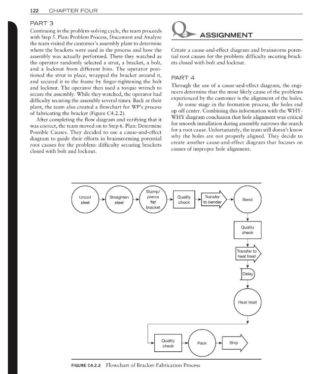
PART 3 Continuing in the problem-solving cycle, the team proceeds with Step 5. Plan: Problem Process, Document and Analyze the team visited the customer's assembly plant to determine where the brackets were used in the process and how the assembly was actually performed. There they watched as the operator randomly selected a strut, a bracket, a bolt, and a locknut from different bins. The operator positioned the strut in place, wrapped the bracket around it, and secured it to the frame by finger-tightening the bolt and locknut. The operator then used a torque wrench to secure the assembly. While they watched, the operator had difficulty securing the assembly several times. Back at their plant, the ream also created a flowchart for WP's process of fabricating the bracket (Figure C4.2.2). After completing the flow diagram and verifying that it was correct, the team moved on to Step 6. Plan: Determine Possible Causes. They decided to use a cause-and-effect diagram to guide their efforts in brainstorming potential root causes for the problem: difficulty securing brackets closed with bolt and locknut. ASSIGNMENT Create a cause-and-effect diagram and brainstorm potential root causes for the problem: difficulty securing brackets closed with bolt and locknut. PART 4 Through the use of a cause-and-effect diagram, the engineers determine that the most likely cause of the problems experienced by the customer is the alignment of the holes. At some stage in the formation process, the holes end up off center. Combining this information with the WHYWHY diagram conclusion that hole alignment was critical for smooth installation during assembly narrows the search for a root cause. Unfortunately, the team still doesn't know why the holes are not properly aligned. They decide to create another cause-and-effect diagram that focuses on causes of improper hole alignment. FIGURE C4.2.2 Hlowchart of Bracket-rabrication I'rocess
ASSIGNMENT Create a second cause-and-effect diagram that focuses on the root causes of improper hole alignment. PAPT 5 At this point in the problem-solving process, it would be appropriate to use statistical information to determine whether the holes are truly not properly aligned. The team would confirm their suspicions during the next production run by having the press operator take samples and measure the angle between the centers of the holes for each sample. This data would then be utilized to create a histogram and compare the process performance with the specification for the angle between insert hole and insert hole of with a tolcrance of . Hole alignment problems are confirmed through the use of histograms in Case Study 4.2, should you choose to use it. Histograms are one of the problem-solving techniques discussed in Step 6. Determining Possible Causes Assuming that hole alignment problems exist and are measurable, the ream continues with their investigation. By srudying the process, they determined that the fixture that holds the flat bracket in place during the bending operation does not securely hold the bracket in place. Changing the bracket fixture will be a relatively expensive undertaking. Although the engineers feel this change would eliminate the root cause of a problem as part of Step 7. Do: Identify, Select, and Implementing the Solution, the team has decided to create a force-field analysis before going to managenent to request funding to make the change. ASSIGNMENT Create a force-field analysis that describes the forces driving the change to the fixture as well as the forces preventing the change from happening. Use your imagination; problem solving is never as simple as "spend money." ASSIGNMENT Describe the remaining steps that the team would take to finish the problem-solving process and ensure that the problem does not return.
Expert Answer
Part 1:
In Part 1 of the case study, the team is tasked with using the WHY-WHY diagram technique to determine why the bracket may be hard to assemble. A WHY-WHY diagram is a tool used in problem-solving to identify the root causes of an issue by repea...