Home /
Expert Answers /
Civil Engineering /
q1-a-roof-beam-shown-in-fig-q1-is-a-w12-65-member-made-from-fy-50-ksi-steel-the-entire-pa997
(Solved): Q1. A roof beam shown in Fig. Q1 is a W12 65 member made from Fy = 50 ksi steel. The entire ...
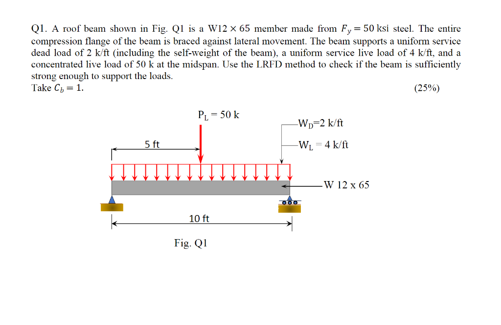
Q1. A roof beam shown in Fig. Q1 is a W12 × 65 member made from Fy = 50 ksi steel. The entire compression flange of the beam is braced against lateral movement. The beam supports a uniform service dead load of 2 k/ft (including the self-weight of the beam), a uniform service live load of 4 k/ft, and a concentrated live load of 50 k at the midspan. Use the LRFD method to check if the beam is sufficiently strong enough to support the loads. Take Cb = 1. (25%) PL = 50 k -Wp-2 k/ft -W? = 4 k/ft 5 ft 10 ft Fig. Q1 -W 12 x 65
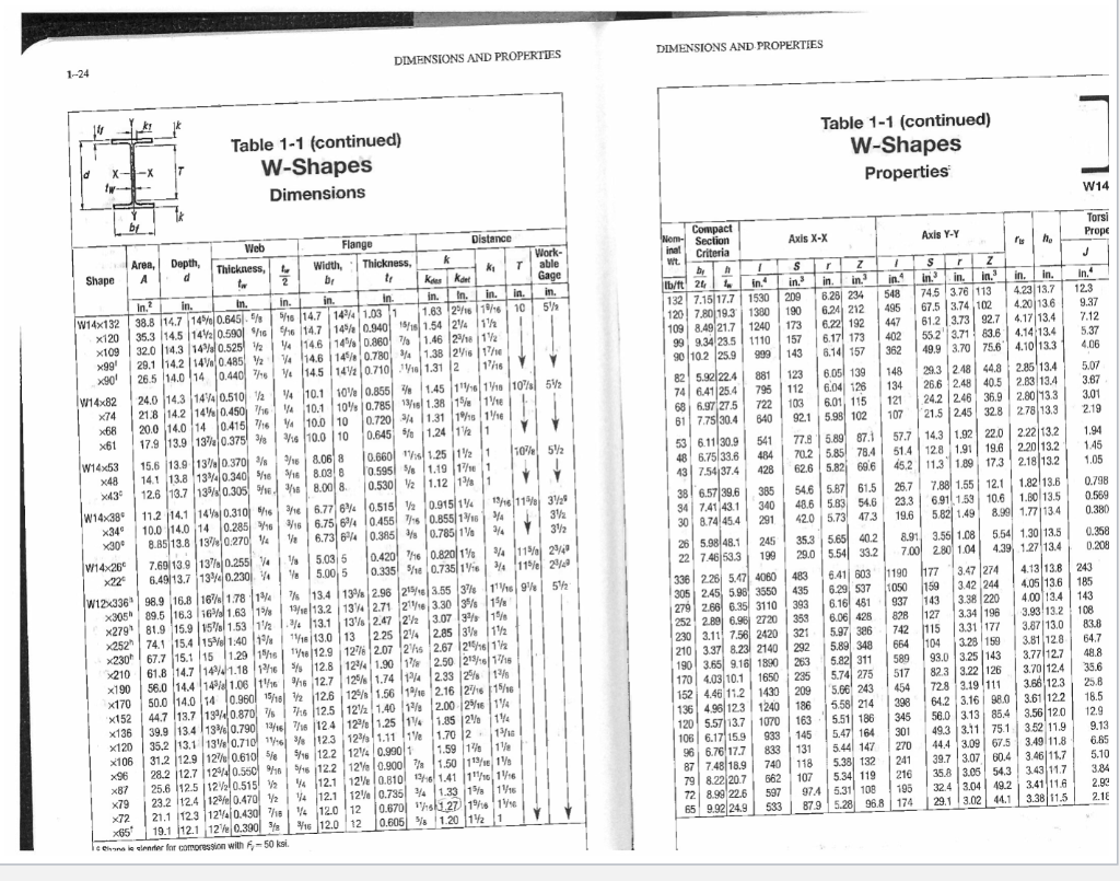
DIMENSIONS AND PROPERTIES Table 1-1 (continued) W-Shapes Dimensions Y te by Web Flange Distance Work- Area, Depth, A d Thickness tu Width, Shape K? 2 tw br k Thickness, "? Kees Kant in. In. in. able Gage in. in. in. in.² in. W14x132 38.8 14.7 14% 0.645.5 in. 5/16 14.7 in. 1.63 216 1/16 5% 35.3 14.5 1420.590 16 x120 x109 32.0 14.3 14% 0.525 2 144 1.03 1 6 14.7 14% 0.940 4 146 14% 0.860 V4 14.6 14% 0.780 14.5 142 0.710 15/16 1.54 24 1 7 1.46 218 12 41.38 26 17/1 18 1.31 2 x99¹ x90¹ 26.5 29.1 14.2 14% 0.485 2 14.0 14 0.440 7/16 14.0 140.440 76 26.5 17/16 1.45 116 118 10% 5% W14x82 Xx74 24.0 14.3 144 0.510/2 21.8 14.2 140.450 16 4 20.0 14.0 14 0.415 7/164 4 10.1 10% 0.855 10.1 10% 0.785 13/18 1.38 15 16 0.720 41.31 115 116 10.0 10 0.645 % 1.24 12 1 16 10.0 10 x68 x61 17.9 13.9 13% 0.375 38 10% 5% 15.6 13.9 13% 0.370 14.1 13.8 13%40.340/16/16 2/16 8.06 8 8.03 8 8.00 8. 12.6 13.7 130.305 16 18 W14x53 x48 x43? W14x38 x34? x30? W14x26 0.660 11.25 1 1 0.595 % 1.19 1 1 0.530 2 1.12 1 1 0.915 1 328 11.2 14.1 14 0.310 16 3/16 10.0 14.0 14 0.285 16 8.85 13.8 137 0.270 14 3½ 0.915 116 115 0.515 2 0.455 716 0.855/13/16 4 3/4 0.385 0.785 1 0.420 16 0.820 1 0.335 18 0.735 16 16 1/8 1/8 3% 13% 0.255 4 3/4 115 25/40 29 1/8 34 115 13% 2.96 21 3.55 37 52 13.4 13/se 13.2 1116 9% 15 7.69 13.9 6.49 13.7 13% 0.230 4 W12x336 98.9 16.8 167 1.78 14 x305 89.5 16.3 16 1.63 15 x279 81.9 15.9 15% 1.53 12 x252 74.1 15.4 15 1:40 19 x230 67.7 15.1 151.29 15/16 x210 61.8 14.7 1441.18 16 x190 134 2.71 21e 3.30 3 13% 2.47 22 3.07 3% 13.1 1% 13 2.25 24 2.85 312 18 13.0 1/16 12.9 1276 2.07 26 2.67 2151612 % 12.8 56.0 14.4 14% 1.06 116 124 1.90 1 2.50 215/16 1/16 125 1.74 14 2.33 25 13/ 12% 1.56 1/16 16 12.7 1/2 12.6 76 12.5 x170 50.0 14.0 14 0.960 15/18 2.16 216 15/16 x152 44.7 13.7 13% 0.870 7 2.00 216 14 1.85 2% 1% 39.9 13.4 13% 0.790 13/16 7/16 124 x136 x120 35.2 13.1 13% 0.710 16 3 12.3 x106 x96 122 1.40 1% 12% 1.25 14 12% 1.11 1e 1.70 2 136 1.59 1 1 31.2 12.9 12% 0.610 5/5/16 12.2 124 0.990 1 5/16 12.2 12% 0.900 71.50 113/1½ 4 12.1 12 0.810 16 1.41 111 116 14 12.1 12% 0.735 4 1.33 1% 116 12 0.670 11 27 16 16 4 12.0 12 3/16 12.0 12 0.605 % 1.20 12 1 28.2 12.7 124 0.550 %18 x87 25.6 12.5 122 0.515 x79 23.2 12.4 12% 0.470 2 x72 21.1 123 124 0.430 718 19.1 12.1 12% 0.390 % x65 cenic clender for compression with F-50 ksi. 1-24 ld X- ky 5 -X - T 6.77 64 6.75 64 6.73 64 5.03 5 5.00, 5 T in. 10 DIMENSIONS AND PROPERTIES Compact Nom-Section inal Axis X-X Wt. Criteria by h I $ lb/ft 24in. in.³ 1530 120 7.80 19.3 1300 24 132 7.15 17.7 209 190 173 157 109 8.49 21.7 99 9.34 23.5 1240 1110 90 10.2 25.9 999 143 82 5.92 22.4 881 74 6.41 25.4 795 68 6.97 27.5 722 61 7.75 30.4 640 53 6.11 30.9 541 48 6.75 33.6 43 7.54 37.4 428 385 340 30 8.74 45.4291 38 6.57 39.6 34 7.41 43.1 26 5.98 48.1 245 199 22 7.46 53.3 336 2.26 5.47 4060 305 2.45 5.96 3550 483 435 393 279 2.66 6.35 3110 252 2.89 6.96 2720 353 230 3.11 7.56 2420 321 292 210 3.37 8.23 2140 263 190 3.65 9.16) 1890 1650 235 1430 209 186 1240 1070 163 933 145 833 131 740 118 662 107 170 4.03 10.1 152 4.46 11.2 136 4.96 123 120 5.57 13.7 106 6.17 15.9 96 6.76 17.7 87 7.48 18.9 79 8.22 20.7 72 8.99 22.6 597 533 65 9.92 24.9 484 Table 1-1 (continued) W-Shapes Properties Axis Y-Y 1 $ rz in. in. in. in.3 74.5 3.76 113 67.5 3.74 102 548 495 447 402 362 61.2 3.73 92.7 55.2 3.71 83.6 49.9 3.70 75.6 29.3 2.48 44.8 26.6 2.48 40.5 148 134 121 107 24.2 246 36.9 21.5 2.45 32.8 57.7 14.3 1.92 22.0 51.4 12.8 1.91 19.6 45.2 11.3 1.89 17.3 26.7 7.88 1.55 12.1 6.91 1.53 10.6 23.3 19.6 5.82 1.49 8.91 3.55 1.08 7.00 2.80 1.04 1190 177 1050 159 937 143 828 127 742 115 Heron r Z in. in.3 6.28 234 6.24 212 6.22 192 6.17 173 6.14 157 6.05 139 123 112 6.04 126 6.01 115 103 92.1 5.98 102 77.8 5.89 87.1 70.2 5.85 78.4 62.6 5.82 69.6 54.6 5.87 61.5 48.6 5.83 54.6 42.0 5.73 47.3 35.3 5.65 40.2 29.0 5.54 33.2 6.41 603 6.29 537 6.16 481 6.06 428 5.97 386 5.89 348 664 104 5.82 311 589 517 5.74 275 454 5.66 243 5.58 214 398 5.51 186 345 301 5.47 164 270 5.44 147 241 5.381 132 216 5.34 119 195 97.4 5.31 108 87.9 5.28 96.8 174 ris ho in. in. 4.23 13.7 4.20 13.6 4.17 13.4 4.14 13.4 4.10 13.3 2.85 13.4 2.83 13.4 2.80 13.3 2.78 13.3 2.22 13.2 2.20 13.2 2.18 13.2 1.82 13.6 1.80 13.5 8.99 1.77 13.4 5.54 1.30 13.5 4.39 1.27 13.4 4.13 13.8 4.05 13.6 4.00 13.4 3.93 13.2 3.87 13.0 3.81 12.8 3.77 12.7 3.70 12.4 3.66 12.3 3.61 12.2 3.56 12.0 3.52 11.9 3.49 11.8 3.46 11.7 3.43 11.7 3.41 11.6 3.38 11.5 3.47 274 3.42 244 3.38 220 3.34 196 3.31 177 3.28 159 93.0 3.25 143 82.3 3.22 126 72.8 3.19 111 64.2 3.16 98.0 56.0 3.13 85.4 49.3 3.11 75.1 44.4 3.09 67.5 39.7 3.07 60.4 35.8 3.05 54.3 32.4 3.04 49.2 29.1 3.02 44.1 - W14 Torsi Prope J in. 12.3 9.37 7.12 5.37 4.06 5.07 3.87 3.01 2.19 1.94 1.45 1.05 0.798 0.569 0.380 0.358 0.208 243 185 143 108 83.8 64.7 48.8 35.6 25.8 18.5 12.9 9.13 6.65 5.10 3.84 2.93 2.18
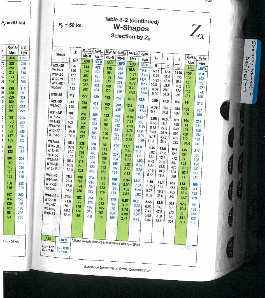
Fy = 50 ksi Vardar $vVax kips kips 4 ASD LRFD 70 227 340 70 251 376 40 212 318 30 171 257 30 199 299 210 315 10 30 199 298 30 220 331 150 225 177 0 186 279 C 0 265 0 197 295 2 176 265 138 207 193 289 3 157 236 ) 155 232 I 181 272 I 123 185 1 204 306 150 225 140 210 172 258 183 275 168 252 146 219 167 252 166 248 129 193 129 193 151 226 171 256 h Fy= 50 ksi; x Table 3-2 (continued) W-Shapes Selection by Zx Fy = 50 ksi Zz Maxl 52 Mx Mod20bMex BF/26BF kip-ft kip-ft kip-ft kips Shape kip-ft 4 4 4? kips in.3 ASD LRFD ASD LRFD ASD LRFD ft ft- in.4 W21x55 126 314 473 192 289 10.8 16.3 1140 156 W14x74 126 314 473 196 2945 6.11 17.4 8.76 31.0 5.31 8.05 795 128 W18x60 123 307 461 189 284 9.62 14.4 5.93 18.2 984 151 W12x79 119 297 446 187 281 3.78 662 117 W14x68 115 287 431 180 39.9 29.3 270 5.19 722 116 W10x88 113 282 424 172 259 2.62 3.94 51.2 534 131 W18x55 112 279 420 172 258 9.15 13.8 17.6 890 141 W21x50 110 274 413 165 248 18.3 13.6 984 158 W12x72 108 269 405 170 256 3.69 5.56 10.7 37.5 597 106 W21x48 107 265 398 162 244 9.89 14.8 6.09 16.5 959 144 W16x57 105 262 394 161 242 7.98 12.0 5,65 18.3 758 141 W14x61 102 254 383 161 242 4.93 7.48 8.65 27.5 640 104 W18x50 101 252 379 155 233 8.76 13.2 5.83 16.9 800 W10x77 128 97.6 244 366 150 225 2.60 45.3 455 112 W12x65 96.8 237 356 154 231 3.90 9.18 5.39 11.9 3.58 35.1 533 W21x44 95.4 238 358 143 214 11.1 16.8 4.45 13.0 843 145 W16x50 92.0 230 345 141 213 7.69 11.4 5.62 17.2 659 124 W18x46 90.7 226 340 138 207 9.63 14.6 4.56 13.7 712 130 W14x53 87.1 217 327 136 204 5.22 6.78 22,3 541 103 W12x58 86.4 216 324 136 205 3.82 8.87 29.8 475 87.8 W10x68 85.3 213 320 132 199 2.58 9.15 40.6 394 97,8 W16x45 82.3 205 309 127 191 7.12 10.8 5.55 16.5 586 111 W18x40 78.4 196 294 119 180 8.94 13.2 4.49 13.1 612 113 W14x48 78.4 196 294 123 184 5.09 7.67 6.75 21.11 484 W12x53 93.8 77.9 194 292 123 185 3.65 5.50 8.76 28.25 425 83.5 W10x60 74.6 186- 280 116 175 2.54 3.82 9.08 36.6 341 85.7 W16x40 73.0 182 274 113 170 6.67 10.0 5.55 15.9 W12x50 518 97.6 71.9 179 270 112 169 3.97 5.98 6.92 23.8 W8x67 391 90.3 70.1 175 263 105 159 1.75 2.59 7.49 47.6 W14x43 272 103 69.6 174 261- 109 164 4.88 7.28 6.68 20.0 W10x54 428 66.6 166 250 105 158 2.48 3.75 9.04 33.6 303 40 Shape exceeds compact limit for flexure with Fy-50 ksi. ASD LRFD 21.67 -0.90 12,-1.50 0,-1.00 12.1 5.67 10.8 7.81 8.69 9.29 5.90 4.59 7.93 5.69 3.85 AMERICAN INSTITUTE OF STEEL CONSTRUCTION Zx Vaxlar Vax kips kips ASD LRFD 234 192 227 175- 174 196 212 237 159 216 212 156 192 169 142 217 186 195 154 132 147 167 169 141 125 129 146 135 154 83.6 125 74.7 112 94.4 Deflection Shears, Moment &
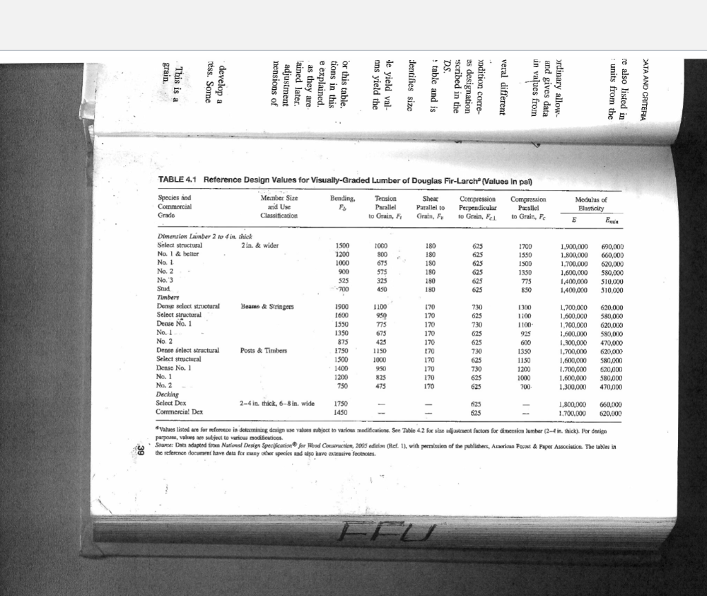
grain. This is a ress. Some develop a nensions of adjustment lained later. as they are- e explained. tions in this or this table. ans yield the le yield val- dentifies size table and is DS. scribed in the es designation ondition corre- veral different in values from and gives data ordinary allow- units from the re also listed in DATA AND CRITERIA TABLE 4.1 Reference Design Values for Visually-Graded Lumber of Douglas Fir-Larch (Values in psi) Comin Species and Commercial Member Size and Use Classification E. Parallel to Grain, Fi Parallel to Dementionin Grain, Fr to Grain, Fel Borella to Grain, F Grade Dimension Lumber 2 to 4 in, thick Select structural 2in. & wider No. 2 No. 3 Timbare Dense select structural Beams & Stringers Select structural Dense No. 1 No 2 Dente select structural Posts & Timbers Select structural Dense No. 1 No 2 Decking Select Dex 2-4 in. thick, 6-8 in. wide 1.800.000 1.700,000 620,00 Commercial Dex Vues listed are for reference in determining design modifications. See Table 4.2 for size adjustment factors for dimension lumber (2-4 in. thick). nick). For desin purposes, values are subject to various modifications alues subject to to Data adapted from National Design Specification for Wood Construction, or species and also have be publishe American Forest & Paper Association. The tables in
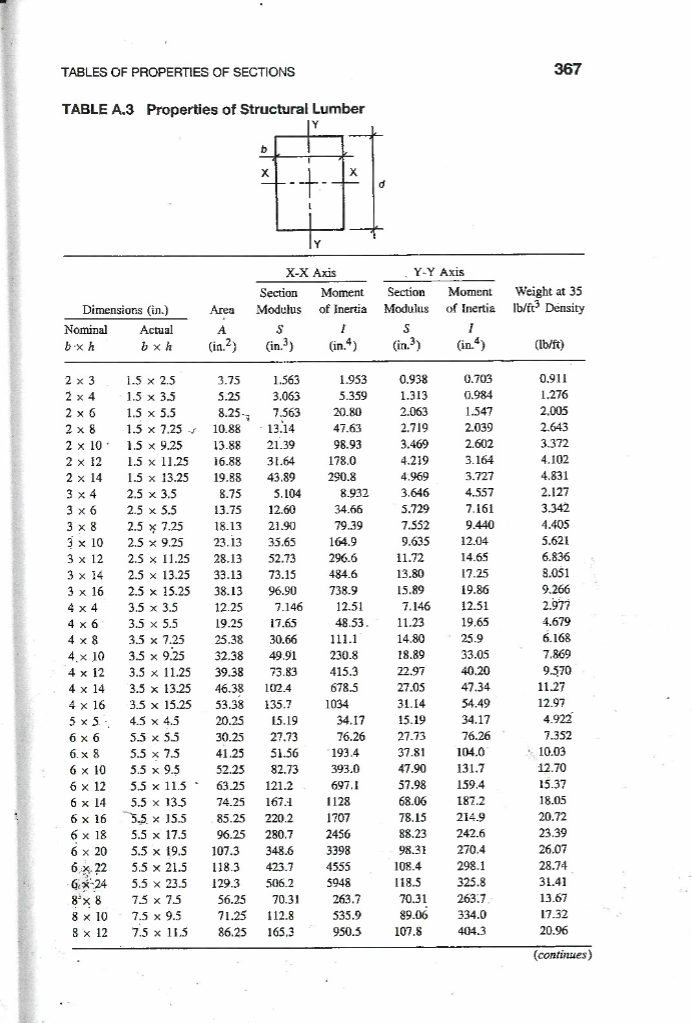
TABLES OF PROPERTIES OF SECTIONS TABLE A.3 Properties of Structural Lumber b X d I Dimensions (in.) Actual bxh 1.5 x 2.5 1.5 x 3.5 1.5 x 5.5 1.5 x 7.25 ? 1.5 x 9.25 1.5 x 11.25 1.5 x 13.25 25×25 2.5 x 3.5 75-55 2.5 x 5.5 MA 2.5 x 7.25 2.5 x 9.25 2.5 x 11.25 2.5 x 13.25 2.5 x 15.25 3.5 x 3.5 3.5 x 5.5 3.5 x 7.25 3.5 x 9.25 3.5 x 11.25 3.5 x 13.25 3.5 x 15.25 4.5 x 4.5 5.5 x 5.5 **** 5.5 x 7.5 Ou 5.5 x 9.5 5.5 x 11.5 Exte 5.5 x 135 5.5 x 15.5 5.5 x 17.5 5.5 x 19.5 5.5 x 21.5 5.5 x 23.5 7.5 x 75 7.5 x 9.5 7.5 x 11.5 Nominal bxh 2 x 3 2 x 4 2 x 6 2 x 8 2 x 2 x 12 2 x 14 3 x 4 3 x 6 3 x 8 10 3 x 10 7.12 3 x 12 205 3 x 14 200 3 x 16 DAN 4 x 4 *** 4 x 6 100 4 x 8 4.x 10 4 x 12 2014 4 x 14 ** 4 x 16 N 5x5. *** 6 x 6 XX 6.x8 6 x 10 6 x 12 6 x 14 6 x 16 6 x 18 6 x 20 6 x 22 GX-24 8 x 8 8 x 10 8 x 12 10. Area ? (in.²) 3.75 5.25 8.25- Y X-X Axis Section Moment Modulus of Inertia S I (in.³) (in.4) 1.563 3.063 7.563 10.88 13.14 13.88 21.39 16.88 31.64 19.88 43.89 8.75 8.75 5.104 13.76 13.75 16 17 18.13 Min 23.13 28.13 200 33.13 38.13 12.25 14:43 24.42 19.25 17.65 www 06.20 25.38 30.66 2000 www 32.38 49.91 **** 39.38 73.83 www Te 46.38 102.4 10:30 www 53.38 135.7 200 www 20.25 zarad 30.25 w 41.25 52.25 *** ww 63.25 121.2 ***** 74.25 167.1 85.25 220.2 96.25 280.7 107.3 348.6 118.3 423.7 129.3 506.2 1260 12.60 11.00 21.90 05 65 35.65 m.m 52.73 ** 73.15 06.00 96.90 5346 7.146 15.19 w 27.73 *** 51.56 82.73 56.25 70.31 71.25 112.8 86.25 165.3 1.953 5.359 20.80 47.63 98.93 178.0 290.8 8932 8.932 34.66 79.39 1640 164.9 206 6 296.6 246 484.6 na n 738.9 12.51 12.51 40 52 48.53. www 111.1 ***** 230.8 wwwww 415.3 **** 678.5 1034 34.17 N 76.26 COM 193.4 393.0 697.1 1128 1707 2456 3398 4555 5948 263.7 535.9 950.5 Y-Y Axis Section Moment Modulus of Inertia S I (in.³) (in.4) 0.938 1.313 2.063 2.719 3.469 4.219 4.969 3.646 3.646 5.729 5.729 7.552 0.625 9.635 1173 11.72 12.90 13.80 15.00 15.89 SUC 7.146 HM 11.23 14.80 14.80 10. 20 18.89 * 22.97 27.05 wwwww 31.14 VATAY 15.19 [[]] 27.73 we 37.81 www 47.90 www 57.98 300 68.06 wwwww 78.15 10:30 88.23 98.31 108.4 118.5 70.31 89.06 107.8 0.703 0.984 1.547 2.039 2.602 3.164 3.727 4.557 7.161 9.440 1201 12.04 14.65 14.65 17.25 10.86 19.86 13.41 12.51 10.45 19.65 25.0 25.9 22.05 33.05 40.20 40.20 MA 47.34 2440 54.49 34.17 76.26 www 104.0 *** 131.7 10** 159.4 2009 187.2 200 214.9 ***** 242.6 270.4 298.1 325.8 263.7- 334.0 404.3 367 Weight at 35 lb/ft³ Density (lb/ft) 0.911 1.276 2.005 2.643 3.372 4.102 4.831 4.631 2.127 2.12 3.342 4.405 5621 5.621 6.836 6.836 8.051 8.051 9266 9.266 2072 2.977 4 670 4.679 6168 6.168 7.860 7.869 0.750 9.570 11.27 13.03 12.97 400 4.922 7.257 7.352 CAM 10.03 www 12.70 26 27 15.37 18.05 20.72 23.39 26.07 28.74 31.41 13.67 17.32 20.96 (continues)