(Solved): Process Control and Instrumentation A CSTR is installed with a temperature feedback control loop for ...
Process Control and Instrumentation
A CSTR is installed with a temperature feedback control loop for
cooling the reactor as shown
in Figure 2.1 to ensure that the reactor will not overheat, and can
be maintained at the optimal
operating condition.
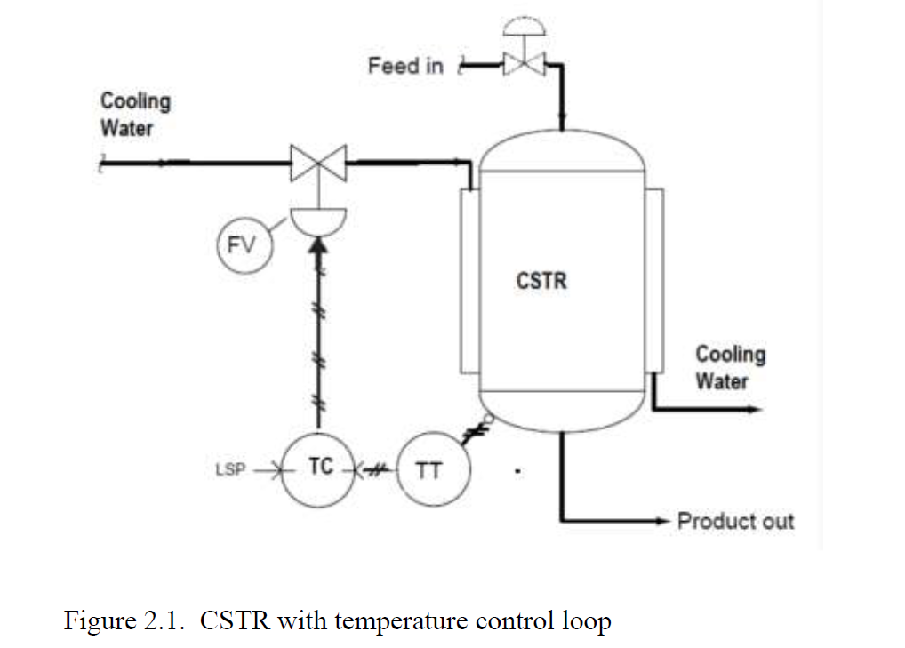
From the information given by the control consultant vendor and
the instrumentation manual,
the dynamics of the valve is very fast compared to the whole
process and the transfer function is
represented as a static gain. The valve has a maximum flow of 12
gal/min. The temperature
transmitter is known to have first order dynamics with a time
constant of 1 min and gain of 1
(psig/ ?C). All instrument signal is pneumatic.
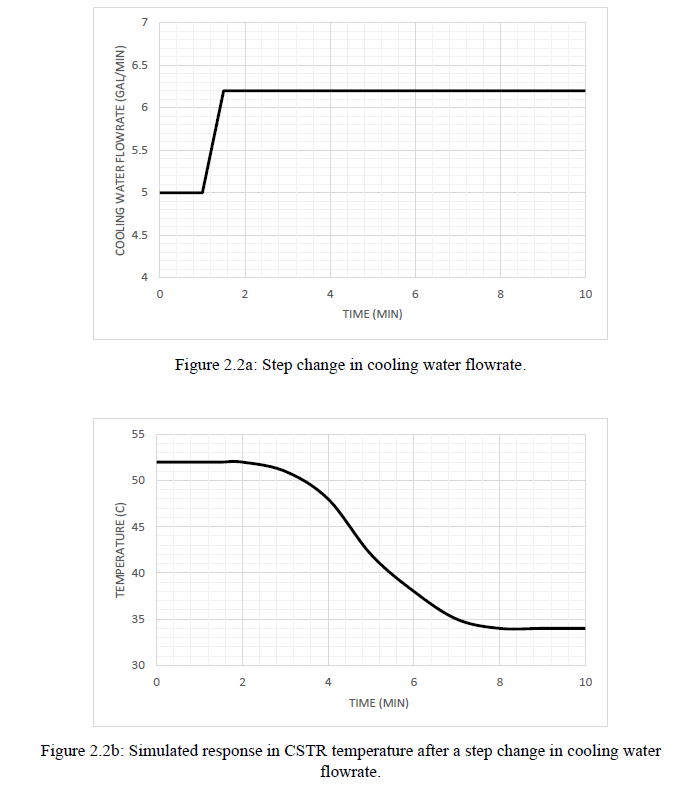
The consultant appointed by the company provided the dynamic
simulation of the CSTR to get
step responses for the temperature. Figure 2.2 shows the CSTR
temperature response with a
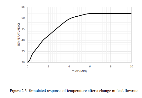
step change in cooling water flow (in gpm) at 1 minute. Figure 2.3
shows the temperature
response after a step change of 1 gal/min in the feed flowrate to
CSTR. From the information
obtained from the consultant, the response of CSTR temperature to a
step change in feed
flowrate is known to be well approximated with a first order model,
while the response of T to
a step change in cooling water flowrate is higher order and can
best be approximated with a
FOPDT model.
a) Based on the step responses, find all the temperature control
system transfer function,
including for all the instrumentation. Show all working. The
working on the graphs for model
estimation must also be clearly shown.
b) Draw the feedback control block diagram. Use a proportional
controller for the system.
Please put in the transfer functions derived in the appropriate
blocks, with the suitable labels
for the variables according to the system.
c) Derive the servo and regulator transfer function for this
closed-loop control system and
analyse the stability of the temperature control system using the
Routh stability criteria. Find
the range of controller gain Kc that make the feedback control
system stable.
d) Find the tuning parameters for the PID controller using the
Cohen Coon method.
Approximate GPRC to a standard form of first order plus dead time
(FOPDT) by setting the
largest ? to become the time constant of the FOPDT model and the
remaining ?’s should be
added up to become the time delay (ie dead time).
e) Determine the offset for servo and regulator problems for the
step change of magnitude 10 ?C
in set point and 2 gal/min in the feed flowrate respectively, if a
proportional controller with the
tuning parameter calculated using the Cohen and Coon method.