Home /
Expert Answers /
Advanced Physics /
procedure-c-converging-lenses-and-the-thin-lens-equation-viewine-screen-position-980-mathrm-c-pa446
(Solved): PROCEDURE C: CONVERGING LENSES AND THE THIN LENS EQUATION Viewine Screen Position \( 980 \mathrm{~c ...
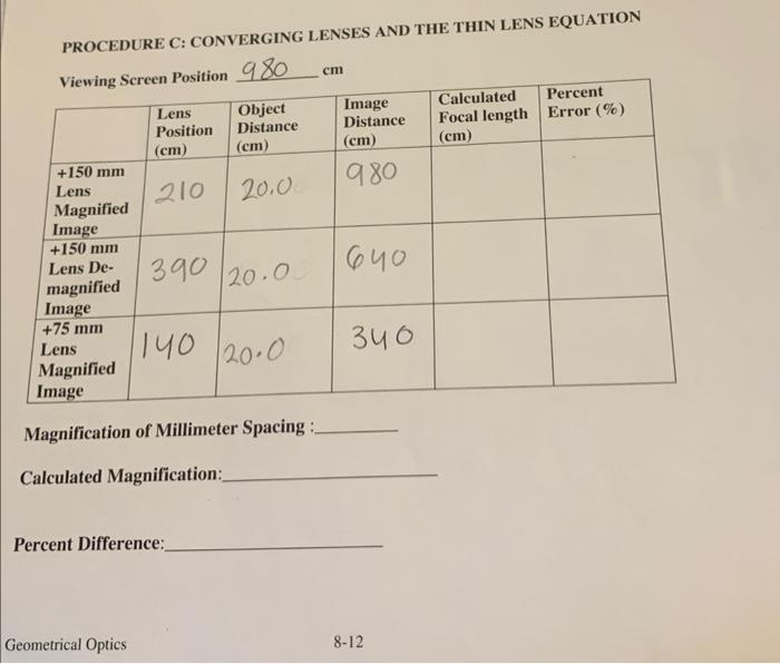
PROCEDURE C: CONVERGING LENSES AND THE THIN LENS EQUATION Viewine Screen Position \( 980 \mathrm{~cm} \) Magnification of Millimeter Spacing : Calculated Magnification: Percent Difference: Geometrical Optics 8-12
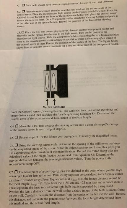
C1. D Each calsle should have two convertine (conves) lenses (75 inm, and 150\( ) \) ?am). C2. I Mace the eptics bench ectender ncar the rero mark ea the yellow scale of the optics bench. Pase the incandescent lieht sosire on the Optics Bench Estender. Phace the Crowed Amow Target on the front of the incadencent holder and place the crossed urrow face at the aero cm mark. On a Componenh Holder atiakb the Viewing Screen and place it at the other end of the optical bench. Recond the position of the face of the viewing C3. \( \square \) Place the 150 man converging (convex) lens on another comgooent holder and place this en the optical bench clone to the light woure. Turn on the power to the incandescent light smarce. Slide the convonent holder containing the lens from a position close to the croised arrow position back to a position where a clear maznified image of the crossed arrow is seen. Record the position of the vertex of the lens. The figure below shows how to measure veriex nositions for a lens on either side of the component holder. From the Crossed Arrow. Viewing Screen , and Lens positions, determine the object and image distances and then calculate the focal length using Equation \( 8.4 \). Determine the peroent error of the experimental determination of the focal length. C4. Move the \( +150 \) lens toxards the vicwing screen until a clear de-magniffed image: of the crossed arrow is seen. Repeat sep \( \mathrm{C} \). C5. \( \square \) Repcat step \( \mathrm{C} 3 \) for the \( 75 \mathrm{~mm} \) converging lens. Find only the magnified image. C6. \( \square \) Using the viewing sereen seale, determine the spacing of the millimeter markings on the magnified image of the arrow, Sinoe the object spacings are \( 1 \mathrm{~mm} \), this gives you the experimental determination of the magnification. Record this value along with the calculaled value of the magnification determined from Equation \( 8.5 \). Detcrmine the percent difference between the two magniufication values. Turn the power to the incandescent lamp OFF. C7. The focal point of a converging lens was delined as the powit where parallel rays converged to after lens refraction. Parallel ray rays can be considered to be from a source an infinite distance away. From Equation \( 8.4 \), if \( d_{\text {chin }}=\infty \), the image distance would be the focal length (dane = 1). Take both the \( +150 \mathrm{~cm} \) and \( +75 \mathrm{~mm} \) lens and a meter stick to a wall opposite the large incandescent light bulb that is supported by a ring stand. Position the lens a distance from the wall so that a sharp image of the bulb filament forms on the wall. Carefully mcasure the distance from the center of the lens to the wall. Record this distance, and calculate the percent crror between the focal length determined from this method and the actual focal length.
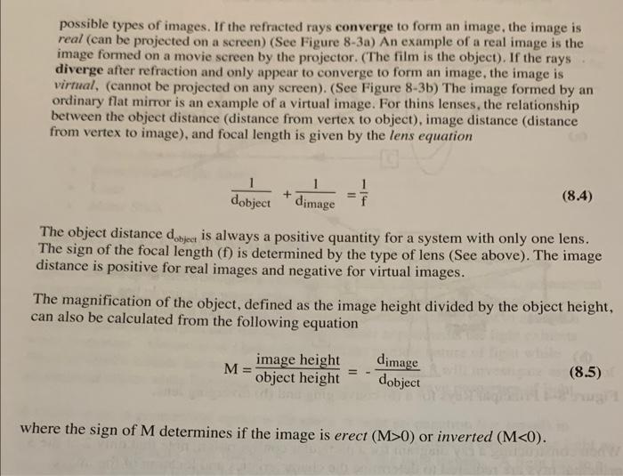
possible types of images. If the refracted rays converge to form an image, the image is real (can be projected on a screen) (See Figure 8-3a) An example of a real image is the image formed on a movie screen by the projector. (The film is the object). If the rays diverge after refraction and only appear to converge to form an image, the image is virmal, (cannot be projected on any screen). (See Figure 8-3b) The image formed by an ordinary flat mirror is an example of a virtual image. For thins lenses, the relationship between the object distance (distance from vertex to object), image distance (distance from vertex to image), and focal length is given by the lens equation \[ \frac{1}{\mathrm{~d}_{\text {object }}}+\frac{1}{\mathrm{~d}_{\text {image }}}=\frac{1}{\mathrm{f}} \] The object distance \( \mathrm{d}_{\text {object }} \) is always a positive quantity for a system with only one lens. The sign of the focal length ( \( f \) ) is determined by the type of lens (See above). The image distance is positive for real images and negative for virtual images. The magnification of the object, defined as the image height divided by the object height, can also be calculated from the following equation \[ \mathrm{M}=\frac{\text { image height }}{\text { object height }}=-\frac{\mathrm{d}_{\text {image }}}{\mathrm{d}_{\text {object }}} \] where the sign of \( M \) determines if the image is erect \( (M>0) \) or inverted \( (M<0) \).