Home /
Expert Answers /
Electrical Engineering /
please-use-multisim-and-show-schematic-2-design-an-active-band-reject-filter-circuit-having-the-pa675
(Solved): Please use multisim and show schematic. 2. Design an active band-reject filter circuit having the ...
Please use multisim and show schematic.
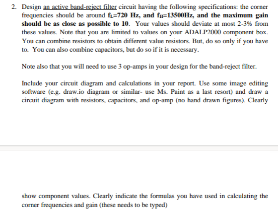
2. Design an active band-reject filter circuit having the following specifications: the corner frequencies should be around , and , and the maximum gain should be as close as possible to 10. Your values should deviate at most 2-3\% from these values. Note that you are limited to values on your ADALP2000 component box. You can combine resistors to obtain different value resistors. But, do so only if you have to. You can also combine capacitors, but do so if it is necessary. Note also that you will need to use 3 op-amps in your design for the band-reject filter. Include your circuit diagram and calculations in your report. Use some image editing software (e.g. draw.io diagram or similar- use Ms. Paint as a last resort) and draw a circuit diagram with resistors, capacitors, and op-amp (no hand drawn figures). Clearly show component values. Clearly indicate the formulas you have used in calculating the corner frequencies and gain (these needs to be typed)
Expert Answer
To design an active band-reject filter circuit with a maximum gain of 10 and corner frequencies around fi=720 Hz and fu=13500Hz, we can use a Multiple