Home /
Expert Answers /
Mechanical Engineering /
part-a-the-drive-shaft-shown-in-fig-3-is-used-to-transmit-300-mathrm-kw-at-600-mathr-pa347
(Solved): Part a: The drive shaft shown in Fig 3 is used to transmit \( 300 \mathrm{~kW} \) at \( 600 \mathr ...
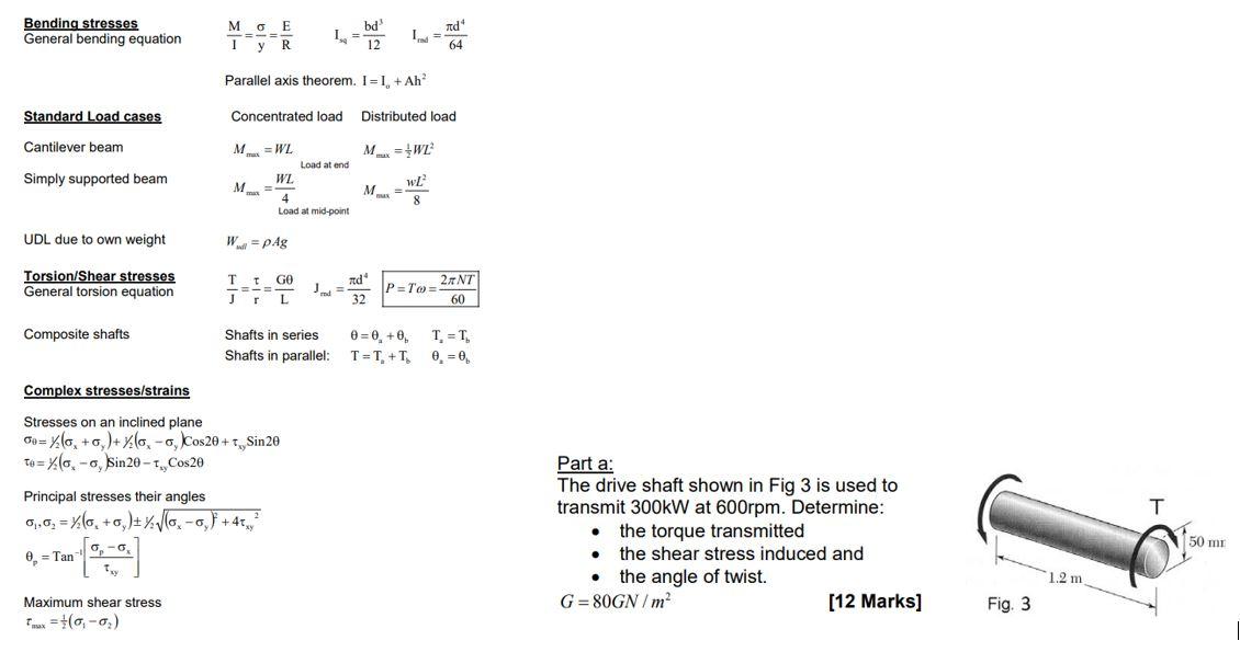
Part a: The drive shaft shown in Fig 3 is used to transmit \( 300 \mathrm{~kW} \) at \( 600 \mathrm{rpm} \). Determine: - the torque transmitted - the shear stress induced and - the angle of twist. \( G=80 G N / m^{2} \) [12 Marks]
Expert Answer
Here in the figure the shaft with 50 mm diameter with torque T acting on it, GIVEN P=300KW N=600 rpm G= 80 GN/m3 we know the formula for power P=2?NT6
