Home /
Expert Answers /
Electrical Engineering /
on-your-breadboard-build-the-circuits-shown-in-figures-5-8-and-5-9-from-the-lab-5-procedure-sheet-pa888
(Solved): On your breadboard, build the circuits shown in Figures 5.8 and 5.9 from the Lab 5 Procedure sheet. ...
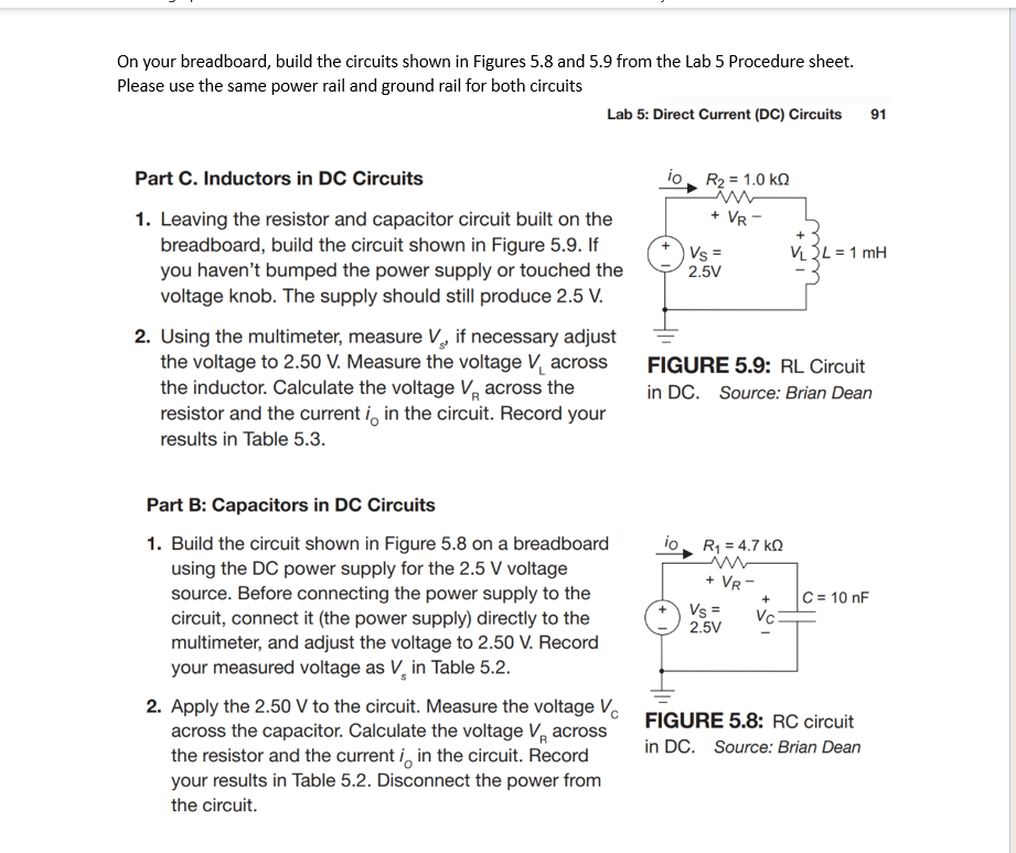
On your breadboard, build the circuits shown in Figures 5.8 and 5.9 from the Lab 5 Procedure sheet. Please use the same power rail and ground rail for both circuits Lab 5: Direct Current (DC) Circuits 91 Part C. Inductors in DC Circuits 1. Leaving the resistor and capacitor circuit built on the breadboard, build the circuit shown in Figure 5.9. If you haven't bumped the power supply or touched the voltage knob. The supply should still produce . 2. Using the multimeter, measure , if necessary adjust the voltage to . Measure the voltage across the inductor. Calculate the voltage across the resistor and the current in the circuit. Record your results in Table 5.3. Part B: Capacitors in DC Circuits 1. Build the circuit shown in Figure 5.8 on a breadboard using the power supply for the voltage source. Before connecting the power supply to the circuit, connect it (the power supply) directly to the multimeter, and adjust the voltage to . Record your measured voltage as in Table 5.2. 2. Apply the to the circuit. Measure the voltage across the capacitor. Calculate the voltage across the resistor and the current in the circuit. Record FIGURE 5.9: RL Circuit in DC. Source: Brian Dean your results in Table 5.2. Disconnect the power from the circuit. FIGURE 5.8: RC circuit in DC. Source: Brian Dean