(Solved): NI myDAQ Measurements Build the circuit of Figure 3.1. Use the myDAQ DMM (digital multimeter) as a v ...
NI myDAQ Measurements
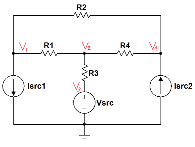
Build the circuit of Figure 3.1. Use the myDAQ DMM (digital multimeter)
as a voltmeter to measure each of the four node voltages.
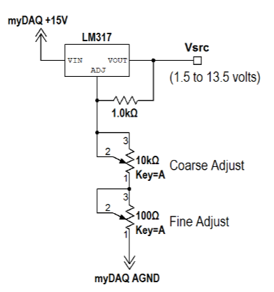
1. Implement the voltage source VSRC according to the circuit diagram
of Figure B.2 on page 164.
2. Measure VSRC with the myDAQ DMM voltmeter and adjust the po-
tentiometer to set the voltage as close to 4.00 volts as possible. Record
the actual voltage you measured.
3. Implement the current source Isrc1 according to the circuit diagram
of Figure B.5 on page 167. Use a 330 ? resistor for the adjustment
resistor R.
4. Measure Isrc1 with the myDAQ DMM ammeter and confirm that the
current is close to 3.79 mA. Record the actual current you measured.
5. Implement the current source Isrc2 according to the circuit diagram
of Figure B.4 on page 166. Use a 680 ? resistor for the adjustment
resistor R.
6. Measure Isrc2 with the myDAQ DMM ammeter and confirm that the
current is close to 1.84 mA. Record the actual current you measured.
Complete the following in multisim
Figure 3.1 below
• Isrc1 = 3.79 mA and Isrc2 = 1.84 mA
• Vsrc = 4.00 V
• R1 = 3.3 k?, R2 = 2.2 k?, R3 = 1.0 k?, and R4 = 4.7 k?
figure B2 Below
Expert Answer
HERE IS YOUR ANSWER! I HOPE

