Home /
Expert Answers /
Electrical Engineering /
nbsp-question-3-please-figure-1-2-figure-1-above-shows-the-single-line-diagram-of-a-three-pha-pa290
(Solved): question 3 please Figure 1 2) Figure 1 above shows the single line diagram of a three pha ...
question 3 please
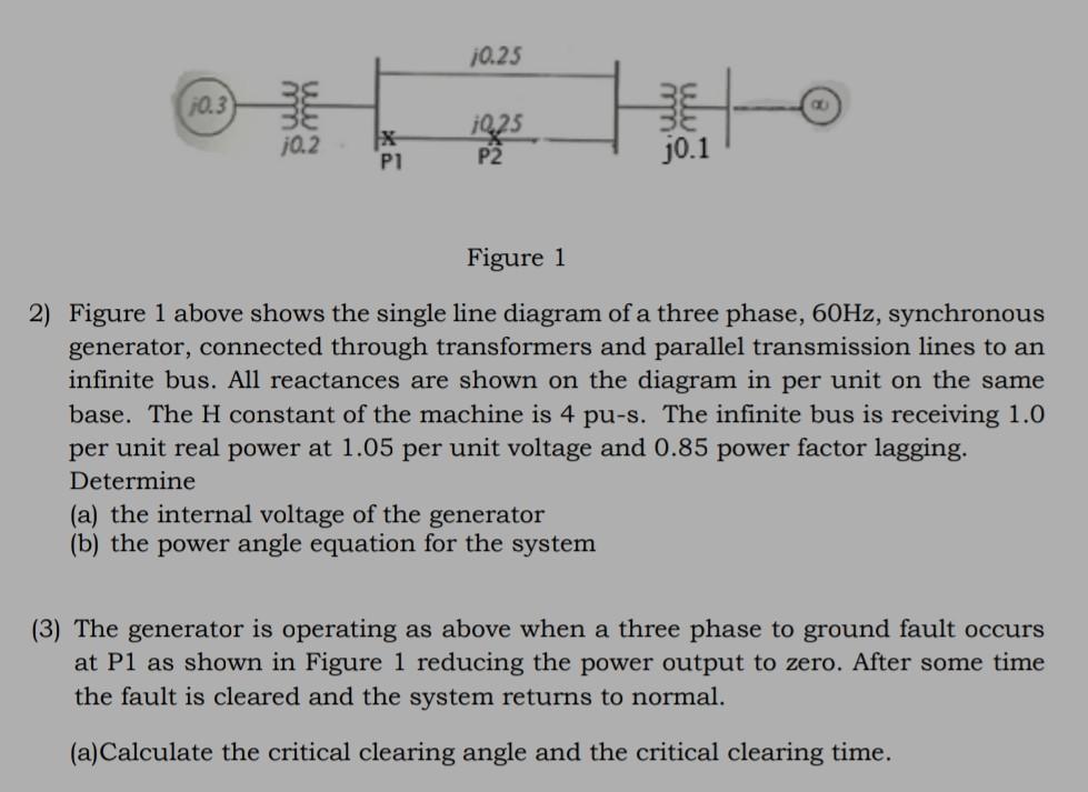
Figure 1 2) Figure 1 above shows the single line diagram of a three phase, \( 60 \mathrm{~Hz} \), synchronous generator, connected through transformers and parallel transmission lines to an infinite bus. All reactances are shown on the diagram in per unit on the same base. The \( \mathrm{H} \) constant of the machine is 4 pu-s. The infinite bus is receiving \( 1.0 \) per unit real power at \( 1.05 \) per unit voltage and \( 0.85 \) power factor lagging. Determine (a) the internal voltage of the generator (b) the power angle equation for the system (3) The generator is operating as above when a three phase to ground fault occurs at P1 as shown in Figure 1 reducing the power output to zero. After some time the fault is cleared and the system returns to normal. (a)Calculate the critical clearing angle and the critical clearing time.
Expert Answer
Solution:- The equivalent circuit for the given probl