Home /
Expert Answers /
Computer Science /
nbsp-q1-figure-1-shows-a-diagram-for-an-automobile-alarm-circuit-used-to-detect-certain-undesi-pa220
(Solved): Q1. Figure 1 shows a diagram for an automobile alarm circuit used to detect certain undesi ...
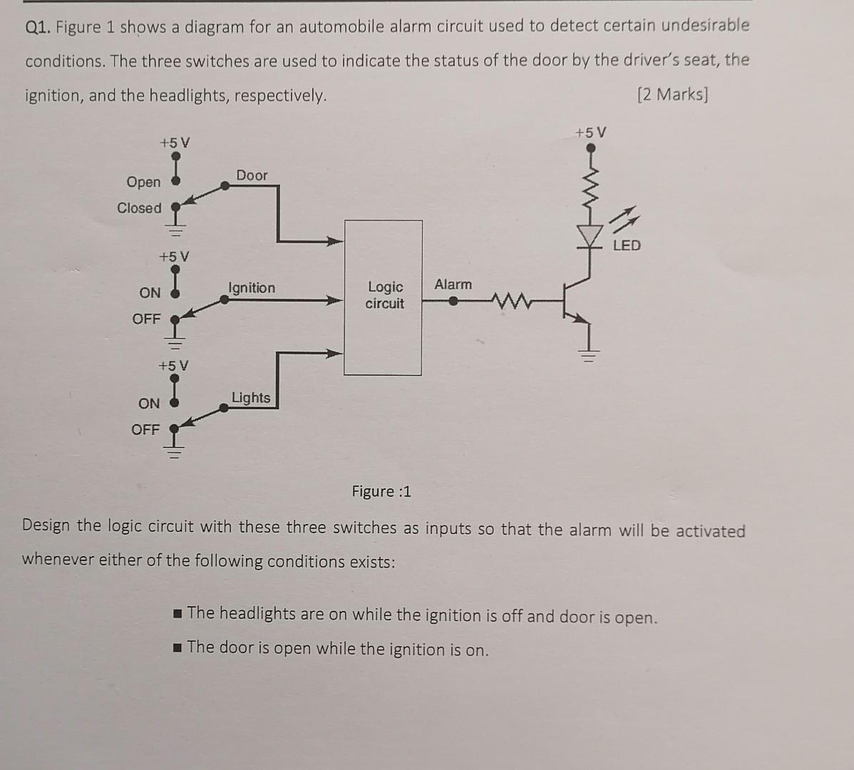
Q1. Figure 1 shows a diagram for an automobile alarm circuit used to detect certain undesirable conditions. The three switches are used to indicate the status of the door by the driver's seat, the ignition, and the headlights, respectively. [2 marks] +5V +5 V Door LED Ignition Alarm Logic circuit Lights ON OFF Figure :1 Design the logic circuit with these three switches as inputs so that the alarm will be activated whenever either of the following conditions exists: The headlights are on while the ignition is off and door is open. The door is open while the ignition is on. Open Closed +5 V ON OFF +5 V