Home /
Expert Answers /
Electrical Engineering /
nbsp-need-all-the-calculations-for-the-impedance-matrix-not-just-the-matrix-nbsp-problem-pa307
(Solved): NEED ALL THE CALCULATIONS FOR THE IMPEDANCE MATRIX , NOT JUST THE MATRIX . Problem: ...
NEED ALL THE CALCULATIONS FOR THE IMPEDANCE MATRIX , NOT JUST THE MATRIX .
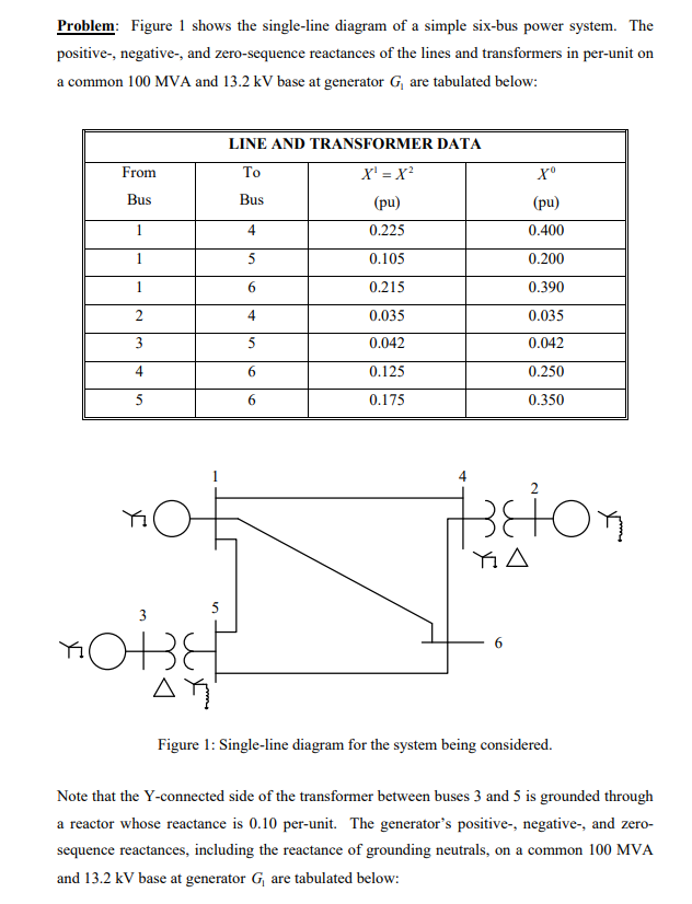
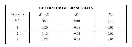
Problem: Figure 1 shows the single-line diagram of a simple six-bus power system. The positive-, negative-, and zero-sequence reactances of the lines and transformers in per-unit on a common 100 MVA and 13.2 kV base at generator G? are tabulated below: From Bus 1 1 1 2 3 4 5 5 3 OBE ?? LINE AND TRANSFORMER DATA To X¹ = X² Bus (pu) 0.225 0.105 0.215 0.035 0.042 0.125 0.175 4 5 6 4 5 6 6 Xº (pu) 0.400 0.200 0.390 0.035 0.042 0.250 0.350 teton ?? 6 Figure 1: Single-line diagram for the system being considered. Note that the Y-connected side of the transformer between buses 3 and 5 is grounded through a reactor whose reactance is 0.10 per-unit. The generator's positive-, negative-, and zero- sequence reactances, including the reactance of grounding neutrals, on a common 100 MVA and 13.2 kV base at generator G, are tabulated below:
Generator No. 1 2 3 GENERATOR IMPEDANCE DATA X¹ = X² (pu) 0.20 0.15 0.25 Xº (pu) 0.06 0.04 0.08 XN (pu) 0.00 0.05 0.00
b) Obtain the positive-, negative-, and zero-sequence bus impedance matrices for this system. c) Determine the fault current for a balanced (30) fault at bus 6 through a fault impedance 2, = j0.05 pu. Find also the voltage at buses 1 and 4, and the current through branch


