Home /
Expert Answers /
Electrical Engineering /
nbsp-nbsp-a-for-the-bjt-configuration-in-the-figure-1-the-following-values-is-given-vcc-pa901
(Solved): (a) For the BJT configuration in the Figure 1, the following values is given Vcc= ...
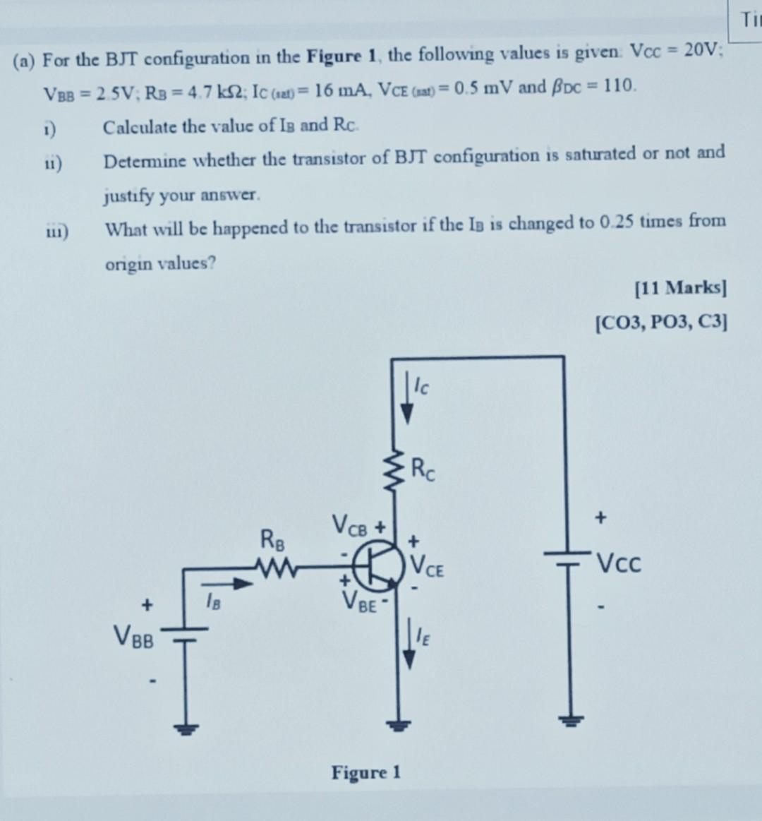
(a) For the BJT configuration in the Figure 1, the following values is given Vcc= 20V; VBB = 2.5V; RB = 4.7 ks2; Ic (at) = 16 mA, VCE (at) = 0.5 mV and Bpc = 110. 1) Calculate the value of IB and Rc. Determine whether the transistor of BJT configuration is saturated or not and justify your answer. What will be happened to the transistor if the IB is changed to 0.25 times from origin values? 111) + VBB RB Vcs + VBE Figure 1 Rc + VCE LE [11 Marks] [CO3, PO3, C3] + Vcc Ti
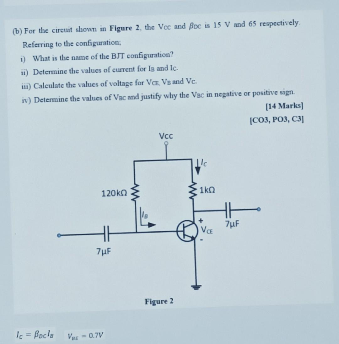
(b) For the circuit shown in Figure 2, the Vcc and Bpc is 15 V and 65 respectively. Referring to the configuration; 1) What is the name of the BJT configuration? ii) Determine the values of current for IB and Ic. iii) Calculate the values of voltage for VCE, VB and Vc. iv) Determine the values of VBC and justify why the VBC in negative or positive sign. [14 Marks] [CO3, PO3, C3] Ic = Bocla VBE 120k? HH 7µF 0.7V Vcc Figure 2 L/c 1kQ VCE 7µF