Home /
Expert Answers /
Electrical Engineering /
nbsp-8-2-a-voltage-divider-bias-circuit-as-in-fig-8-24-has-the-following-componen-pa994
(Solved): 8-2 A voltage-divider bias circuit (as in Fig. 8-24) has the following componen ...
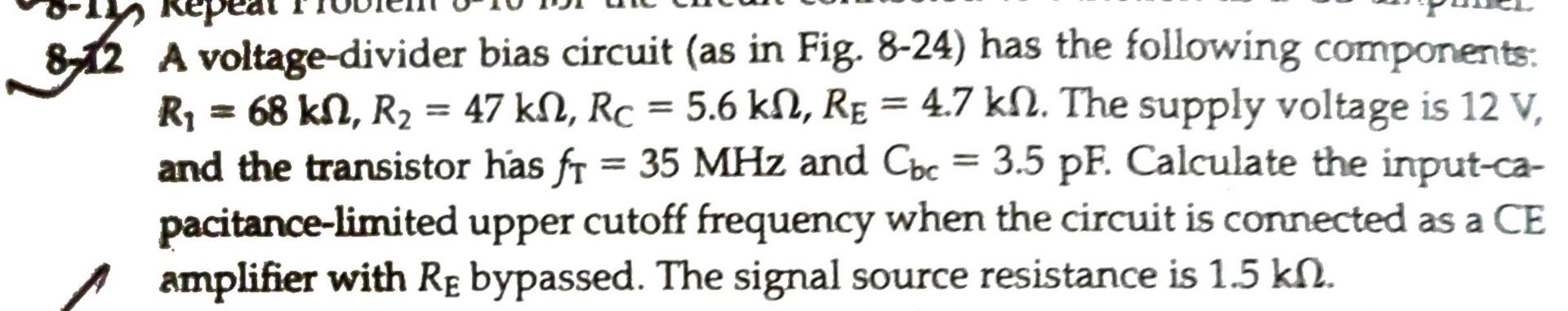
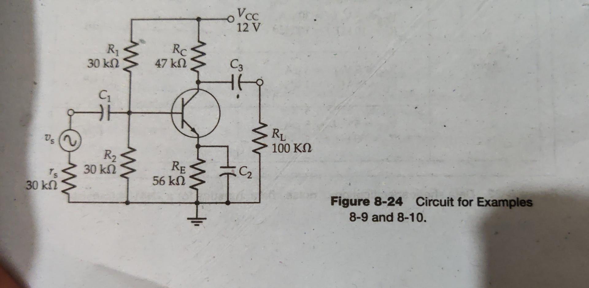
8-2 A voltage-divider bias circuit (as in Fig. 8-24) has the following components: \( R_{1}=68 \mathrm{k} \Omega, R_{2}=47 \mathrm{k} \Omega, R_{C}=5.6 \mathrm{k} \Omega, R_{E}=4.7 \mathrm{k} \Omega \). The supply voltage is \( 12 \mathrm{~V} \), and the transistor has \( f_{\mathrm{T}}=35 \mathrm{MHz} \) and \( \mathrm{C}_{\mathrm{bc}}=3.5 \mathrm{pF} \). Calculate the input-capacitance-limited upper cutoff frequency when the circuit is connected as a CE amplifier with \( R_{E} \) bypassed. The signal source resistance is \( 1.5 \mathrm{k} \Omega \).
Figure 8-24 Circuit for Examples 8-9 and 8-10.