Home /
Expert Answers /
Computer Science /
nbsp-1-1-the-diagram-below-is-a-multi-bit-full-adder-with-two-overflow-detector-circuits-thi-pa283
(Solved): 1. 1- The diagram below is a multi-bit full adder with two overflow detector circuits. Thi ...
1.
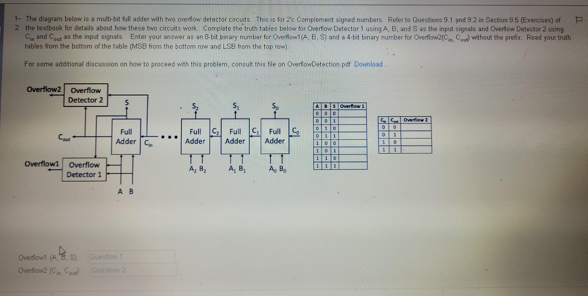
1- The diagram below is a multi-bit full adder with two overflow detector circuits. This is for 2 'c Complement signed numbers. Refer to Ouestions \( 9.1 \) and \( 9.2 \) in Section \( 9.5 \) (Exercises) of 2. the textbook for details about how these two circuits work. Complete the truth tables below for Overflow Detector 1 using A., B, and \( S \) as the input signals and Owerflow Detector 2 using tables from the bottom of the table (MISE from the bottom row and LSB from the top row). For some additional discussion on how to proceed with this problem, consult this file on OverflowDetection. pdf Downiload.
Expert Answer
FIRSTLY IF YOU HAVE ANY QUERIES PLEASE ASK IN COMMENTS SECTION