Home /
Expert Answers /
Electrical Engineering /
microprocessor-nbsp-a-a-logic-gates-circuit-shown-in-figure-below-represents-an-arm-cortex-m0-c-pa312
(Solved): MICROPROCESSOR (a) A logic gates circuit shown in Figure below represents an ARM Cortex M0+ c ...
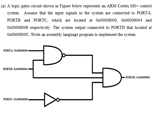
(a) A logic gates circuit shown in Figure below represents an ARM Cortex M0+ control system. Assume that the input signals to the system are connected to PORTA, PORTB and PORTC, which are located at 0x00008000, 0x00008004 and 0x00008008 respectively. The system output connected to PORTD that located at 0x0000800C. Write an assembly language program to implement the system PORTA: 0x00008000 PORTB: 0x00008004 • PORTD: 0x0000800C PORTC: 0x00008008
Expert Answer
Solution :: arrow_forward Step 1 Introduction to Assembly Language Program It is defined as a low-level programming language for a computer or other programmable device specific to a particular computer architecture in contrast to m