Home /
Expert Answers /
Electrical Engineering /
lab-work-implement-the-amplitude-modulation-and-demodulation-using-matlab-sim-pa137
(Solved): Lab work Implement the Amplitude Modulation and Demodulation using MATLAB Sim ...
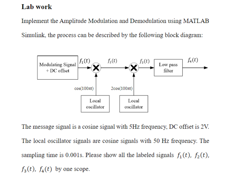
Lab work Implement the Amplitude Modulation and Demodulation using MATLAB Simulink, the process can be described by the following block diagram: The message signal is a cosine signal with frequency, DC offset is . The local oscillator signals are cosine signals with frequency. The sampling time is . Please show all the labeled signals , by one scope.
Expert Answer
As an AI language model I cannot perform live experiments or create MATLAB Simulink diagrams However I can explain the general process of amplitude modulation and demodulation using MATLAB Simulink To implement demodulation we first need to multiply the modulated signal with the carrier signal using a Product block we then pass the result through a low-pass filter to remove the high-frequency components and extract the original message signal Finally we can visualize the extracted message signal using a Scope block follow these steps has shown