Home /
Expert Answers /
Mechanical Engineering /
in-the-following-diagram-the-bar-element-2-is-used-to-stiffen-the-cantilever-beam-element-1-3-ba-pa579
(Solved): In the following diagram, the bar element 2 is used to stiffen the cantilever beam element 1: 3 Ba ...
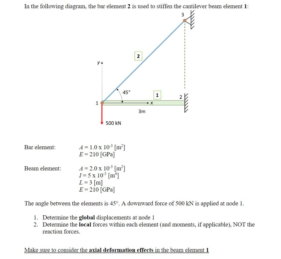
In the following diagram, the bar element 2 is used to stiffen the cantilever beam element 1: 3 Bar element: YA Beam element: 1 500 KN 45° A = 1.0 x 10-³ [m²] E = 210 [GPa] 2 3m X 1 N TWITT A = 2.0 x 10¹³ [m²] I= 5 x 10¹5 [m²] L=3 [m] E = 210 [GPa] The angle between the elements is 45°. A downward force of 500 kN is applied at node 1. 1. Determine the global displacements at node 1 2. Determine the local forces within each element (and moments, if applicable), NOT the reaction forces. Make sure to consider the axial deformation effects in the beam element 1