Home /
Expert Answers /
Physics /
in-the-circuit-shown-in-the-following-figure-figure-1-the-capacitor-has-capacitance-17-mu-ma-pa594
(Solved): In the circuit shown in the following figure(Figure 1) the capacitor has capacitance \( 17 \mu \ma ...
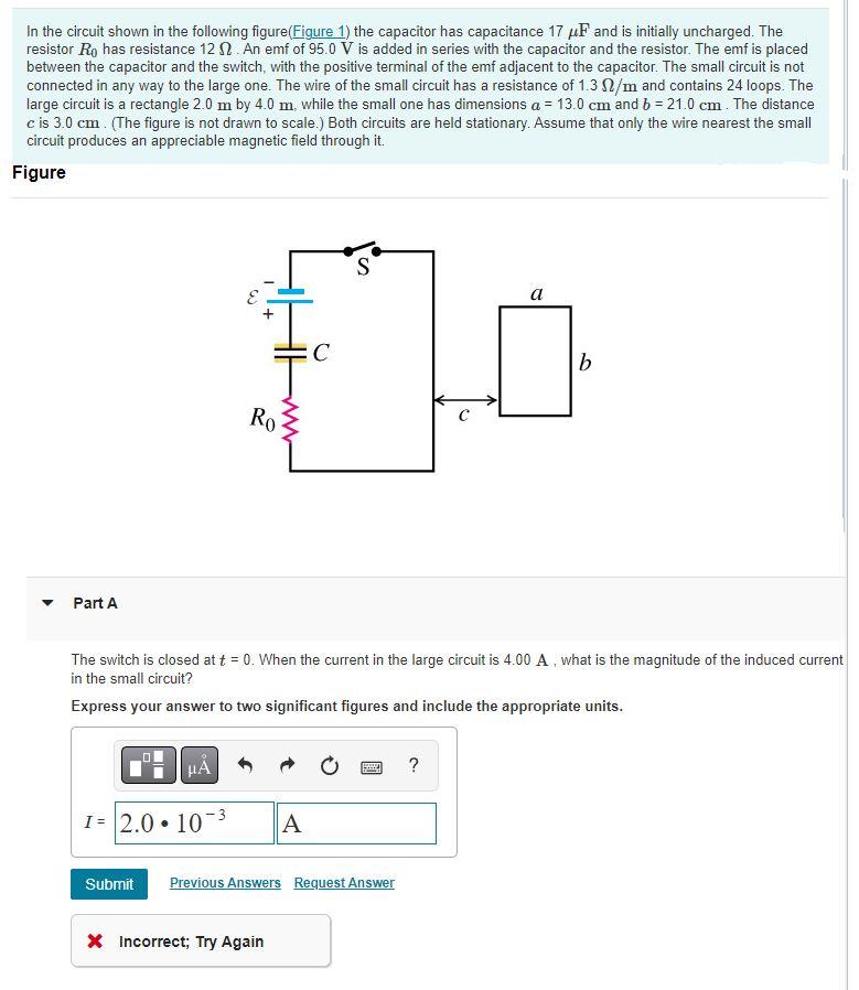
In the circuit shown in the following figure(Figure 1) the capacitor has capacitance \( 17 \mu \mathrm{F} \) and is initially uncharged. The resistor \( R_{0} \) has resistance \( 12 \Omega \). An emf of \( 95.0 \mathrm{~V} \) is added in series with the capacitor and the resistor. The emf is placed between the capacitor and the switch, with the positive terminal of the emf adjacent to the capacitor. The small circuit is not connected in any way to the large one. The wire of the small circuit has a resistance of \( 1.3 \Omega / \mathrm{m} \) and contains 24 loops. The large circuit is a rectangle \( 2.0 \mathrm{~m} \) by \( 4.0 \mathrm{~m} \). while the small one has dimensions \( a=13.0 \mathrm{~cm} \) and \( b=21.0 \mathrm{~cm} \). The distance \( c \) is \( 3.0 \mathrm{~cm} \). (The figure is not drawn to scale.) Both circuits are held stationary. Assume that only the wire nearest the small circuit produces an appreciable magnetic field through it. Figure Part A The switch is closed at \( t=0 \). When the current in the large circuit is \( 4.00 \mathrm{~A} \), what is the magnitude of the induced current in the small circuit? Express your answer to two significant figures and include the appropriate units.
Expert Answer
Time constant ?=RC?=17×10?6×12?=2.04×10
