Home /
Expert Answers /
Electrical Engineering /
in-the-circuit-shown-in-fig-1-t-is-s-practical-transformer-whose-turns-ratio-n1-pa202
(Solved): In the circuit shown in Fig. 1,T is s practical transformer whose turns ratio n1 ...
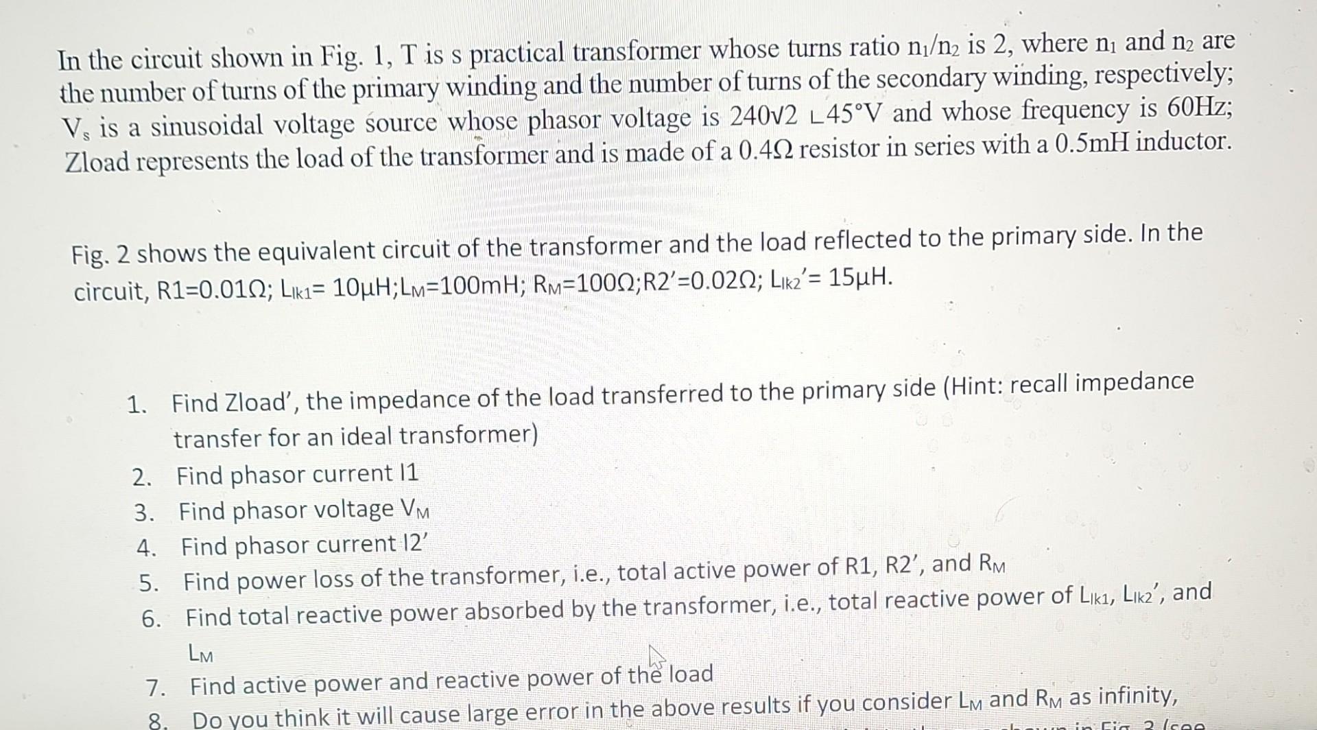
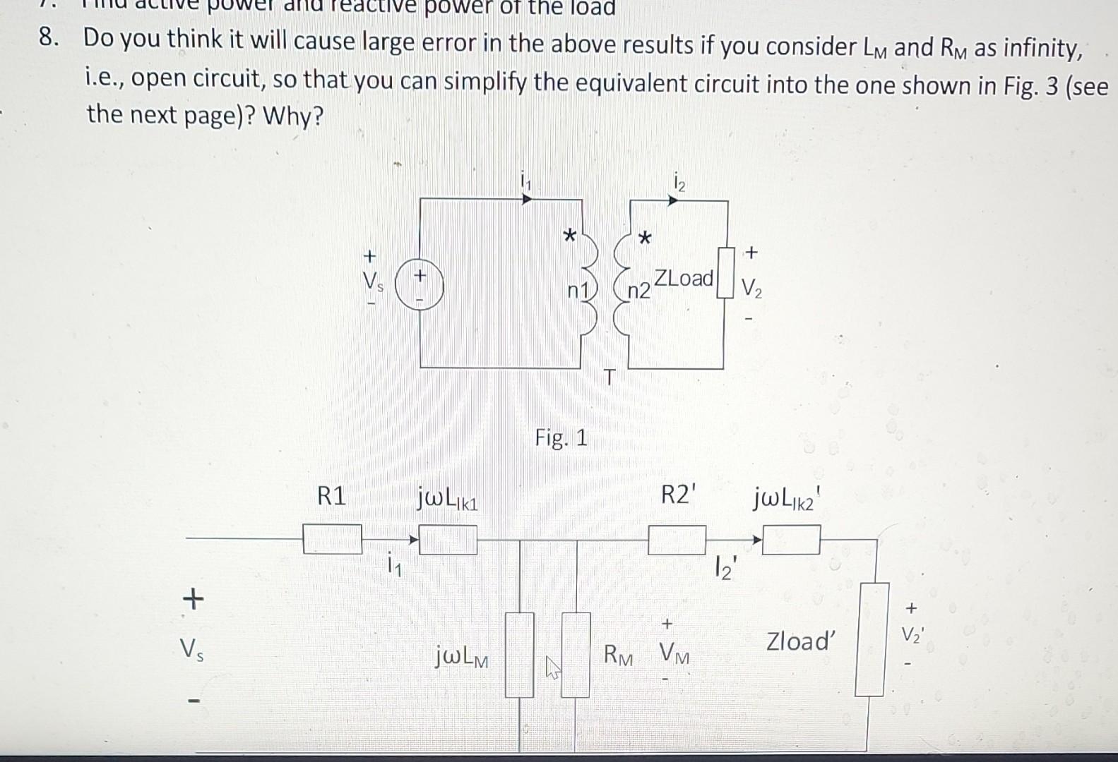
In the circuit shown in Fig. is s practical transformer whose turns ratio is 2 , where and are the number of turns of the primary winding and the number of turns of the secondary winding, respectively; is a sinusoidal voltage source whose phasor voltage is \( 240 \mathrm{v} 2\left\llcorner 45^{\circ} \mathrm{V}\right. \) and whose frequency is ; Zload represents the load of the transformer and is made of a resistor in series with a inductor. Fig. 2 shows the equivalent circuit of the transformer and the load reflected to the primary side. In the circuit, . 1. Find Zload', the impedance of the load transferred to the primary side (Hint: recall impedance transfer for an ideal transformer) 2. Find phasor current 3. Find phasor voltage 4. Find phasor current 12' 5. Find power loss of the transformer, i.e., total active power of , and 6. Find total reactive power absorbed by the transformer, i.e., total reactive power of , and 7. Find active power and reactive power of the load
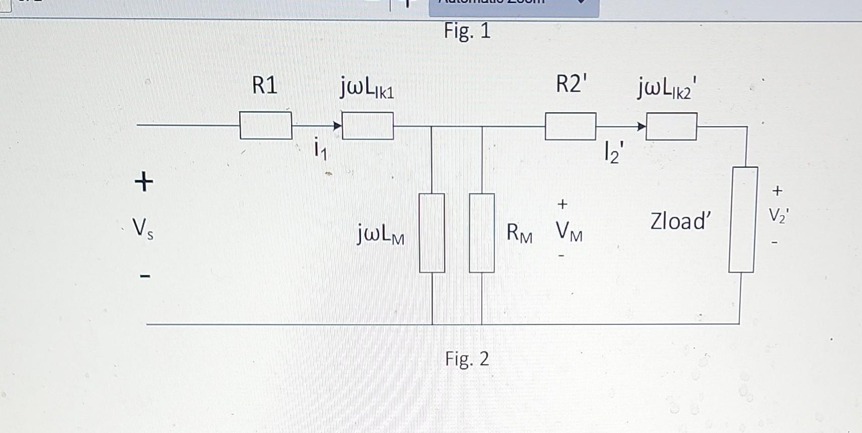
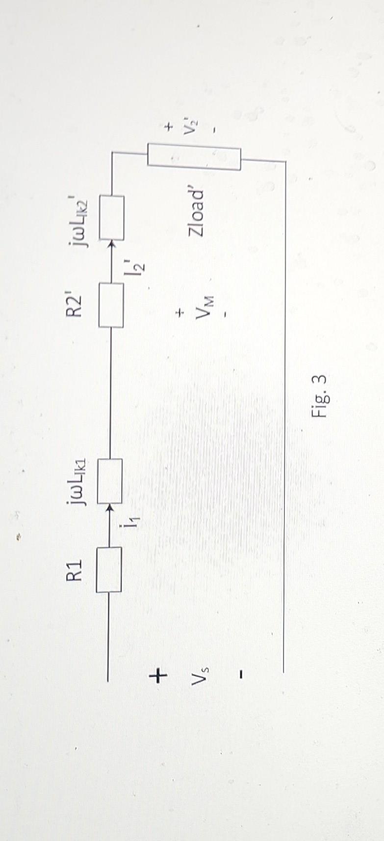
8. Do you think it will cause large error in the above results if you consider and as infinity, i.e., open circuit, so that you can simplify the equivalent circuit into the one shown in Fig. 3 (see the next page)? Why? Fig. 1
Fig. 1 Fig. 2
Fig. 3
Expert Answer
I have provided the ans In Images