Home /
Expert Answers /
Civil Engineering /
in-order-to-support-a-focused-load-from-the-girder-a-w14-x-233-is-used-as-a-column-the-length-of-t-pa435
(Solved): In order to support a focused load from the girder, a W14 x 233 is used as a column. The length of t ...
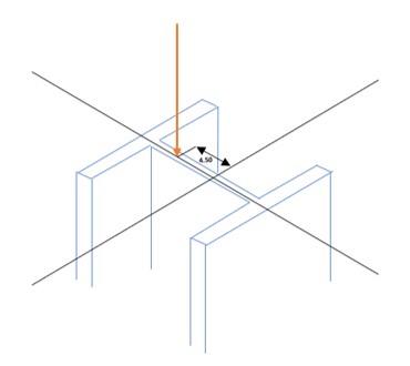
In order to support a focused load from the girder, a W14 x 233 is used as a column. The length of the column is 7.5 ft. The girder's load is made up of a live load and a 70 kips dead load. According to the illustration, the concentrated load is 4.5 inches off center. Use the section's Fy=50ksi, Fu=65ksi, Qa=0.85, Qs=0.9, and Cb=1.0 parameters as needed. By using LRFD determine the following: (a) maximum live load a column can support while considering compression only. (b) maximum live load that a column can support considering the biaxial bending.
Refer to the table below for the additional properties:
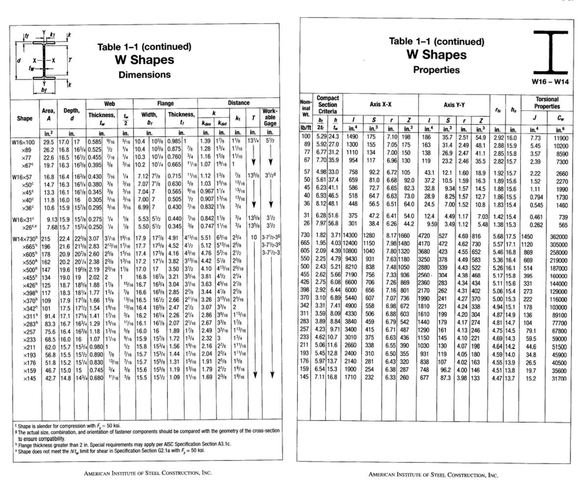
d fw- --X by Shape A Area, Depth, d x233 AKOO x211 x193 T x455" 134 x426" 125 426 125 x176 x159 x145 Table 1-1 (continued) W Shapes Dimensions Web Thickness, 9.13 15.9 15% 0.275 4 7.68 15.7 15% 0.250 4 x283 83.3 16.7 164 1.29 15/16 63.316.710741291716 x257 75.6 16.4 16% 1.18 13/16 1.07 116 1.07 to 2 in. in. in.² in. W16x100 29.5 17.0 17 0.585 %/16 0.585 %/16 5/16 10.4 x89 26.2 16.8 164 0.525 4 10.4 x77 22.6 16.5 14 10.3 x67c 3/16 10.2 104 0.665 116 1.07 1916 1 W16x57 x50 x45€ 0.715 0.630 0.565 %/16 0.505 2 x40€ x36€ W16x31 x26 W14x730 215 x665 196 x605 178 x550 162 162 0.455 716 19.7 16.3 16% 0.395 % 16.8 16.4 16% 0.430 7/16 47.12 7% 14.7 16.3 164 0.380/8/16 7.07 7 13.3 16.1 16% 0.345 % %/16 7.04 7 11.8 16.0 16 0.305 %/16 3/16 7.00 7 0.430 716 10.6 15.9 15% 0.295 5/16 3/16 6.99 7 15.53 52 0.440 7/16 1/8 5.50 52 0.345 % 1916 17.9 17 4.91 415/16 213/16 1716 17.7 17% 4.52 42 2% 15/16 17.4 17% 4.16 28 1/16 17.2 174 3.82 3.50 19.6 19% 2.19 216 1 17.0 17 16.8 16% 3.21 22.4 22% 3.07 316 21.6 21% 2.83 20.9 20% 2.60 20.2 2014 2.38 x500 147 19.0 19 2.02 2 19.0 19 2.02 2 1 18.7 18% 1.88 16 15/16 16.7 7/8 16.6 Flange 68.5 16.0 16 06.5 10.0 62.0 15.7 154 0.980 1 Width, b? K? T Kdes Ket Work- able Gage in. in. in. in. in. in. in. 10% 0.985 1 1.39 1% 1% 13% 5% 10% 0.875 7 1.28 14 116 104 0.760 34 1.16 15 116 Thickness, tr 398h 117 X398" 117 18.3 184 1.77 13 16.5 X370 109 x342 101 X342 101 16% 2.85 27 17.9 17% 1.66 15/13/16 16.5 16/2 2.66 17.5 172 1.54 1916 13/16 16.4 16% 2.47 x311 91.4 17.1 17% 1.41 17/16 4 16.2 164 2.26 24 1/16 16.1 16% 2.07 216 1716 10.11078 207 208 % k 116 1.12 13a 5/8 1.03 15/16 0.967 14 0.907 13/16 0.832 1 0.842 1 0.747 1/16 Distance 5.51 616 234 5.12 513/16 25 416 4.76 516 2/2 313/16 4.42 5 2 32 4.10 413/16 25/16 316 3.81 4 2 16% 3.04 3/16 3.63 45/16 26 3.44 4 218 21/16 3.26 315/162/16 22 3.07 34 2 2.86 316 115/16 2.67 38 18 201 16.0 16172 1% 2.32 3 1.89 18 2.49 316 113/16 v 16 15.9 158 14 134 101532166 186 216 27/117/18 1/2 15.8 154 1.56 1916 2.16 27 111/16 7/16 15.7 15% 1.44 1/16 2.04 24 11/16 7/16 15.7 15% 1.31 15/16 1.91 25/8 15 / 15.6 15% 1.19 13/16 1.79 22 19/16 42.7 14.8 144 0.680 16 3/8 15.5 152 1.09 116 1.69 23 1916 56.8 15.5 152 0.890 78 51.8 15.2 15% 0.830 13/16 46.7 15.0 15 0.745 4 a 13% 329 13/16 13/16 13/16 3/4 3/4 135/8 3/2 3/4 135/8 3/2 h Flange thickness greater than 2 in. Special requirements may apply per AISC Specification Section A3.1c. Shape does not meet the h't, limit for shear in Specification Section G2.1a with F, 50 ksi. AMERICAN INSTITUTE OF STEEL CONSTRUCTION, INC. Shape is slender for compression with F= 50 ksi. The actual size, combination, and orientation of fastener components should be compared with the geometry of the cross-section to ensure compatibility. 10 3-72-39 3-712-3 3-72-3 Compact Section Criteria br h lb/ft 24 1 100 5.29 24.3 89 5.92 27.0 77 67 Nom- inal Wt. 6.77 31.2 7.70 35.9 57 4.98 33.0 50 5.61 37.4 45 6.23 41.1 40 6.93 46.5 36 8.12 48.1 I 31 6.28 51.6 26 7.97 56.8 758 659 586 518 448 375 301 H in.4 1490 175 1300 155 1110 134 954 117 209 398 2.02 545000 2.92 6.44 6000 370 3.10 6.89 5440 342 3.31 7.41 4900 311 3.50 9.00 4220 311 3.59 8.09 282 290 294 2940 283 3.89 8.84 3840 Axis X-X 122 971 2100 3400 S r Z in.3 in. in.3 7.10 198 7.05 175 7.00 150 6.96 130 47.2 6.41 54.0 38.4 6.26 44.2 730 1.82 3.71 14300 1280 665 1.95 4.03 12400 1150 605 2.09 4.39 10800 1040 550 2.25 4.79 9430 931 500 242 500 2.43 5.21 8210 455 2.60 5.60 7400 455 2.62 5.66 7190 838 756 426 2.75 6.08 6600 125 2.75 609 6600 700 706 92.2 6.72 105 81.0 6.68 92.0 Fr 72.7 6.65 82.3 64.7 6.63 73.0 56.5 6.51 64.0 Table 1-1 (continued) W Shapes Properties Cre 656 COT 607 550 558 FAC 4330 506 257 4.23 9.71 2010 233 4.62 10.7 3010 229 211 5.06 11.6 2660 338 310 193 5.45 12.8 2400 176 5.97 13.7 2140 281 159 6.54 15.3 1900 254 145 7.11 16.8 1710 232 8.17 1660 7.98 1480 7.80 1320 7.63 1180 7.48 1050 720 000 7.33 936 7.06 060 7.26 869 716 001 7.16 801 12.4 9.59 4720 527 4170 472 3680 423 378 3250 MA 2880 339 0 5600 2560-304 0000 000 2360 283 0170 2170 1000 co 1990 1000 1810 1010 6.88 603 1610 ka 1440 1200 1290 450 459 HE 00000 6.79 542 6.71 407 6.71 487 6.6? 126 6.63 436 375 200 415 ATE 262 M 241 POR 221 P 199 K 179 HA 161 1150 145 100 1030 130 931 119 838 107 748 96.2 4.00 146 677 6.55 390 6.50 355 6.43 320 6.38 287 6.33 260 4.02 163 87.3 3.98 133 HJ 7.07 726 7.07 736 6.00 670 6.98 672 0.00000 1 in. Axis Y-Y S r in.3 in. 35.7 2.51 31.4 2.49 48.1 54.9 26.9 2.47 41.1 23.2 2.46 35.5 Z in.3 186 163 138 119 43.1 12.1 1.60 18.9 37.2 10.5 1.59 10.5 1.59 16.3 32.8 9.34 1.57 14.5 28.9 8.25 1.57 12.7 24.5 7.00 1.52 10.8 4.49 1.17 3.49 1.12 4.69 816 4.62 730 4.55 652 4.49 583 000 4.43 522 4.38 468 4.34 434 D 4.31 402 27 270 4.27 370 404 200 4.24 338 PIN 4.20 304 ro 4.17 274 4.13 246 4.10 201 4.10 221 VOX 200 4.07 198 4.05 180 ho in. in. 2.92 16.0 2.88 15.9 7.03 1.42 15.4 5.48 1.38 15.3 2.85 15.8 2.82 15.7 1.92 15.7 1.89 15.6 1.88 15.6 1.86 15.5 1.83 15.4 I W16 - W14 5.00 15.3 1151 4.94 15.1 AMERICAN INSTITUTE OF STEEL CONSTRUCTION, INC. J in.4 7.73 5.45 3.57 2.39 2.22 1.52 5.68 17.5 1450 5.57 17.1 1120 869 669 5.46 16.8 5.36 16.4 506161 5.26 16.1 514 4101 Torsional Properties 1.11 0.794 0.545 5.17 15.8 395 244120204 5.11 15.6 219091 5.06 15.4 273 331 222 0.461 0.262 178 136 4.87 14.9 401427 4.81 14.7 104 **** 4.75 14.5 4.69 14.3 4.64 14.2 14.6 4.59 14.0 4.55 13.9 4.51 13.8 4.47 13.7 79.1 59.5 44.6 34.8 26.5 19.7 15.2 Cw in.6 11900 10200 8590 7300 2660 2270 1990 1730 1460 739 565 362000 305000 258000 219000 €15000 187000 160000 ***000 144000 100000 129000 **0000 116000 110000 103000 105000 89100 09100 77700 11700 67800 0000 59000 30000 51500 45900 40500 35600 31700