Home /
Expert Answers /
Electrical Engineering /
i-need-to-simulate-the-mosfet-driver-circuit-which-includes-zener-diodes-and-bjts-as-shown-in-the-fi-pa945
(Solved): I need to simulate the mosfet driver circuit which includes zener diodes and BJTs as shown in the fi ...
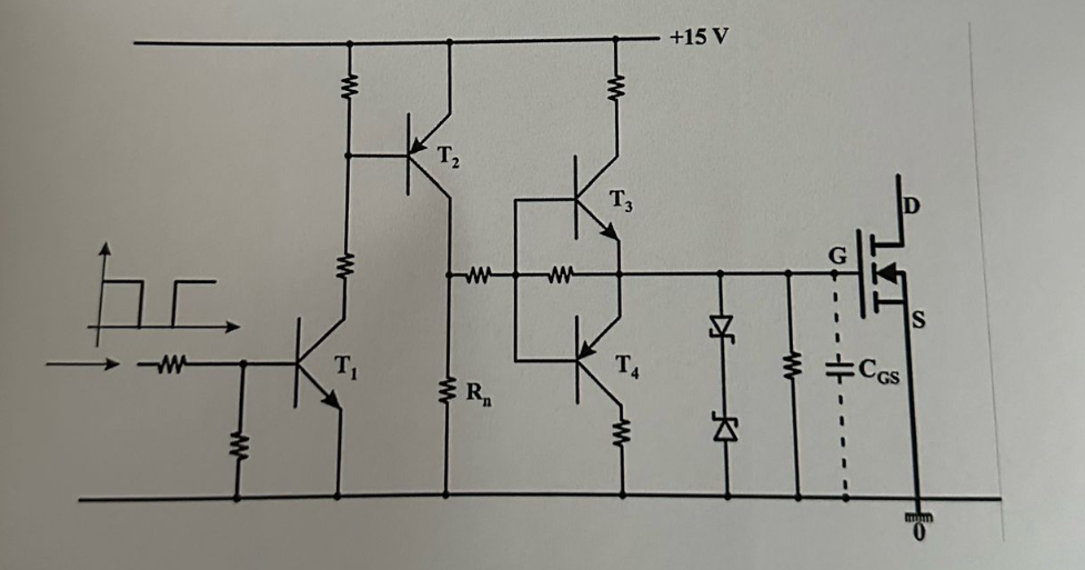
I need to simulate the mosfet driver circuit which includes zener diodes and BJTs as shown in the figure. Can you post screenshots of the circuits in action simulated on LTSPice or proteus? In this driving circuit, when the input signal is applied, T1, T2 and T3 enter into conduction sequentially and the G end is pulled to +15 V. When the input signal is cut off, T4 enters conduction through the resistor R, and pulls the G terminal to 0, that is, it discharges the MOSFET's parasitic input capacitor CGS.