Home /
Expert Answers /
Mechanical Engineering /
i-need-the-solution-asap-i-upvote-100-machine-design-the-turning-moment-diagram-shown-in-fig-pa495
(Solved): I need the solution Asap I upvote 100 % (Machine design) The turning moment diagram, shown in Fig. ...

(Machine design)
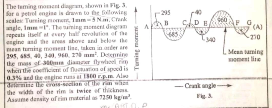
The turning moment diagram, shown in Fig. \( 3 . \) for a petrol engine is drawn to the following scales: Turning moment, \( 1 \mathbf{m m}=5 \) N.m; Crank angle, \( 1 \mathbf{m m}=1^{\circ} \). The turning moment diagram repeats itself at every half revolution of the engine and the areas above and below the mean turning moment line, taken in order are \( 295,685,40,340,960,270 \mathrm{~mm}^{2} \). Determine the mass of \( 300 \mathrm{~mm} \) diameter flywheel rim when the coefficient of fluctuation of speed is \( 0.3 \% \) and the engine runs at 1800 r.p.m. Also determine the cross-section of the rim when the width of the rim is twice of thickness. Assume density of rim material as \( 7250 \mathrm{~kg} / \mathrm{m}^{3} \)