Home /
Expert Answers /
Computer Science /
h-select-connections-from-the-bottom-left-hand-comer-choose-a-copper-straight-through-cable-typ-pa481
(Solved): h. Select Connections from the bottom left-hand comer. Choose a copper straight-through cable typ ...
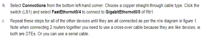

h. Select Connections from the bottom left-hand comer. Choose a copper straight-through cable type. Click the switch (LS1) and select FastEthernet0/4 to connect to GigabitEthernet0/0 of Rtr1. Repeat these steps for all of the other devices until they are all connected as per the diagram in figure 1. Note when connecting 2 routers together you need to use a cross-over cable because they are like devices, ie both are DTEs. Or you can use a serial cable.
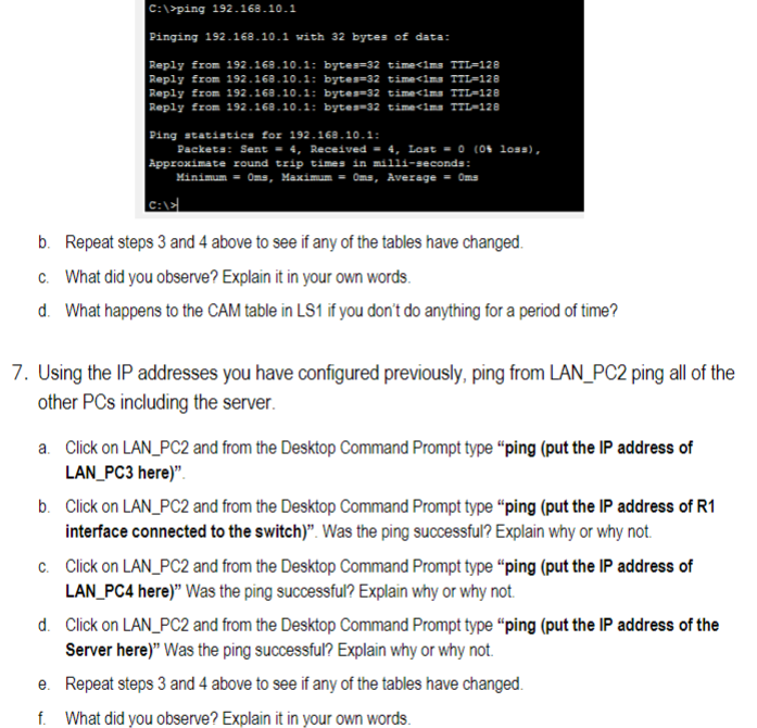
C: lyping 192.168.10.1 Pinging 192.168 .10 .1 with 32 bytes of data: Reply from 192.168.10.1: byteg=32 timeclmg TTL=128 Reply from 192.169.10.1: bytes=32 time<1mn TTL=128 Reply from 192.169.10.1; bytes=32 time<1ma TTL-128 Reply from 192.169.10.1; bytes-32 time<1ma ITL-12B Ping statiatics for 192.168 .10 .1 : Packets: Sent , Received , Loat , Approximate round trip times in mili-geconds: Minimum me, Maximum ans, Average c: b. Repeat steps 3 and 4 above to see if any of the tables have changed. C. What did you observe? Explain it in your own words. d. What happens to the CAM table in LS1 if you don't do anything for a period of time? 7. Using the IP addresses you have configured previously, ping from LAN_PC2 ping all of the other PCs including the server. a. Click on LAN_PC2 and from the Desktop Command Prompt type "ping (put the IP address of LAN_PC3 here)". b. Click on LAN_PC2 and from the Desktop Command Prompt type "ping (put the IP address of R1 interface connected to the switch)". Was the ping successful? Explain why or why not. c. Click on LAN_PC2 and from the Desktop Command Prompt type "ping (put the IP address of LAN_PC4 here)" Was the ping successful? Explain why or why not. d. Click on LAN_PC2 and from the Desktop Command Prompt type "ping (put the IP address of the Server here)" Was the ping successful? Explain why or why not. e. Repeat steps 3 and 4 above to see if any of the tables have changed. f. What did you observe? Explain it in your own words.
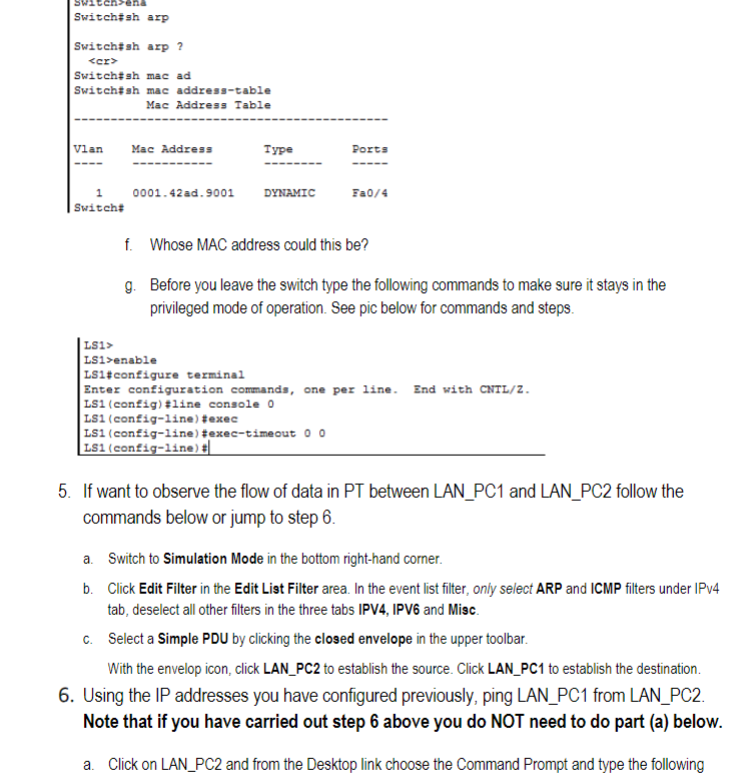
f. Whose MAC address could this be? g. Before you leave the switch type the following commands to make sure it stays in the privileged mode of operation. See pic below for commands and steps. LS1> LS1>enable Ls1\#configure terminal Enter configuration commands, one per line. End with Cart/Z. LS1 (config) tline console 0 LS1 (config-1ine) texec LS1 (config-line) texec-timeout 00 Ls1 (config-1ine) *! 5. If want to observe the flow of data in PT between LAN_PC1 and LAN_PC2 follow the commands below or jump to step 6 . a. Switch to Simulation Mode in the bottom right-hand corner. b. Click Edit Filter in the Edit List Filter area. In the event list filter, only select ARP and ICMP filters under IPV4 tab, deselect all other filters in the three tabs IPV4, IPV6 and Misc. c. Select a Simple PDU by clicking the closed envelope in the upper toolbar. With the envelop icon, click LAN_PC2 to establish the source. Click LAN_PC1 to establish the destination. 6. Using the IP addresses you have configured previously, ping LAN_PC1 from LAN_PC2. Note that if you have carried out step 6 above you do NOT need to do part (a) below. a. Click on LAN_PC2 and from the Desktop link choose the Command Prompt and type the following
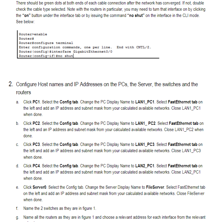
There should be green dots at both ends of each cable connection after the network has converged. If not, double check the cable type selected. Note with the routers in particular, you may need to turn that interface on by clicking the "on" button under the interface tab or by issuing the command "no shut" on the interface in the CLI mode. See below: Router>enable Router Router?configure terminal Bnter configuration commands, one per line. End with CNTL/Z. Router (config) \#interface GigabitZtherneto/0 Router (config-if) \#no shut 2. Configure Host names and IP Addresses on the PCs, the Server, the switches and the routers a. Click PC1. Select the Config tab. Change the PC Display Name to LAN1_PC1. Select FastEthernet tab on the left and add an IP address and subnet mask from your calculated available networks. Close LAN1_PC1 when done. b. Click PC2. Select the Config tab. Change the PC Display Name to LAN1_PC2. Select FastEthernet tab on the left and an IP address and subnet mask from your calculated available networks. Close LAN1_PC2 when done. c. Click PC3. Select the Config tab. Change the PC Display Name to LAN1_PC3. Select FastEthernet tab on the left and add an IP address and subnet mask from your calculated available networks. Close LAN1_PC3 when done. d. Click PC4. Select the Config tab. Change the PC Display Name to LAN2_PC1. Select FastEthernet tab on the left and add an IP address and subnet mask from your calculated available networks. Close LAN2_PC1 when done. e. Click Servero. Select the Config tab. Change the Server Display Name to FileServer. Select FastEthernet tab on the left and add an IP address and subnet mask from your calculated available networks. Close FileServer when done. f. Name the 2 switches as they are in figure 1 . g. Name all the routers as they are in figure 1 and choose a relevant address for each interface from the relevant
command when you see the prompt C:I>"ping (put the IP address of LAN_PC1 here)" and you should see something similar to the pic below
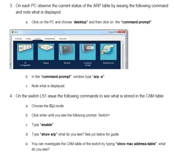
3. On each PC observe the current status of the ARP table by issuing the following command and note what is displayed. a. Click on the PC and choose "desktop" and then click on the "command prompt" b. In the "command prompt" window type "arp -a" c. Note what is displayed. 4. On the switch LS1 issue the following commands to see what is stored in the CAM table a. Choose the mode b. Click enter until you see the following prompt: Switch> c. Type "enable" d. Type "show arp" what do you see? See pic below for guide e. You can investigate the CAM table of the switch by typing "show mac address-table". what do you see?
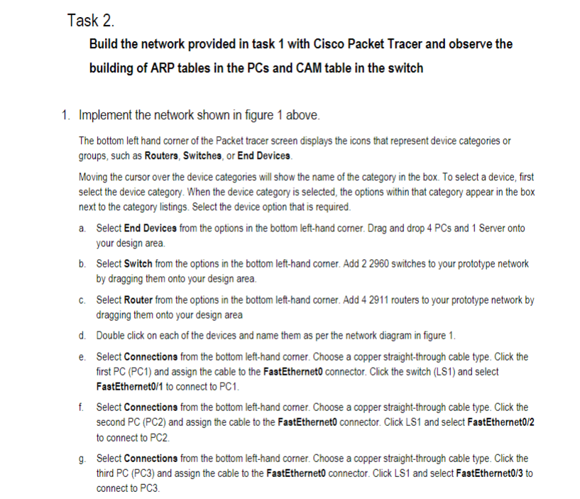
Task 2. Build the network provided in task 1 with Cisco Packet Tracer and observe the building of ARP tables in the PCs and CAM table in the switch 1. Implement the network shown in figure 1 above. The bottom left hand corner of the Packet tracer screen displays the icons that represent device categories or groups, such as Routers, Switches, or End Devices. Moving the cursor over the device categories will show the name of the category in the box. To select a device, first select the device category. When the device category is selected, the options within that category appear in the box next to the category listings. Select the device option that is required. a. Select End Devices from the options in the bottom left-hand corner. Drag and drop 4 PCs and 1 Server onto your design area. b. Select Switch from the options in the bottom left-hand corner. Add 22960 switches to your prototype network by dragging them onto your design area. c. Select Router from the options in the bottom left-hand corner. Add 42911 routers to your prototype network by dragging them onto your design area d. Double click on each of the devices and name them as per the network diagram in figure 1. e. Select Connections from the bottom left-hand corner. Choose a copper straight-through cable type. Click the first PC (PC1) and assign the cable to the FastEthernet0 connector. Click the switch (LS1) and select FastEthernet0/1 to connect to PC1. f. Select Connections from the bottom left-hand corner. Choose a copper straight-through cable type. Click the second PC (PC2) and assign the cable to the FastEthernet0 connector. Click LS1 and select FastEthernet0/2 to connect to PC2. g. Select Connections from the bottom left-hand corner. Choose a copper straight-through cable type. Click the third PC (PC3) and assign the cable to the FastEthernet0 connector. Click LS1 and select FastEthernet0/3 to connect to PC3.