Home /
Expert Answers /
Mechanical Engineering /
free-power-cooling-water-out-gas-generator-turbine-turbine-compressor-5-1-load-pre-cooler-2-4-6-co-pa342
(Solved): Free power Cooling water out Gas generator turbine turbine Compressor 5 1 Load Pre cooler 2 4 6 Co ...
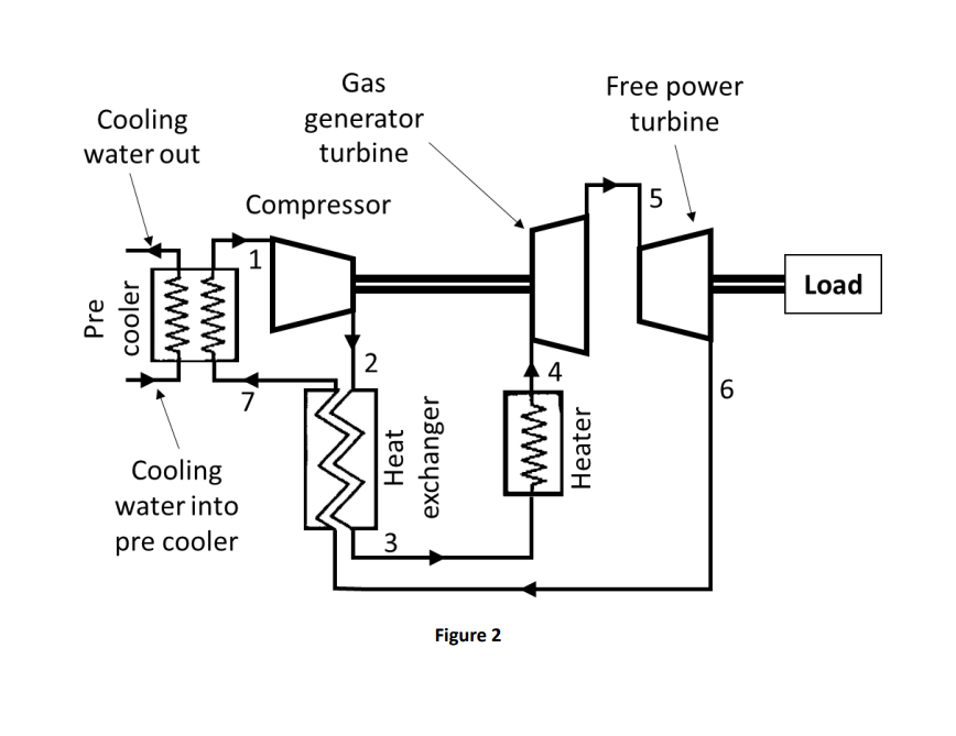
Free power Cooling water out Gas generator turbine turbine Compressor 5 1 Load Pre cooler 2 4 6 Cooling water into pre cooler Heat exchanger Heater 3 Figure 2
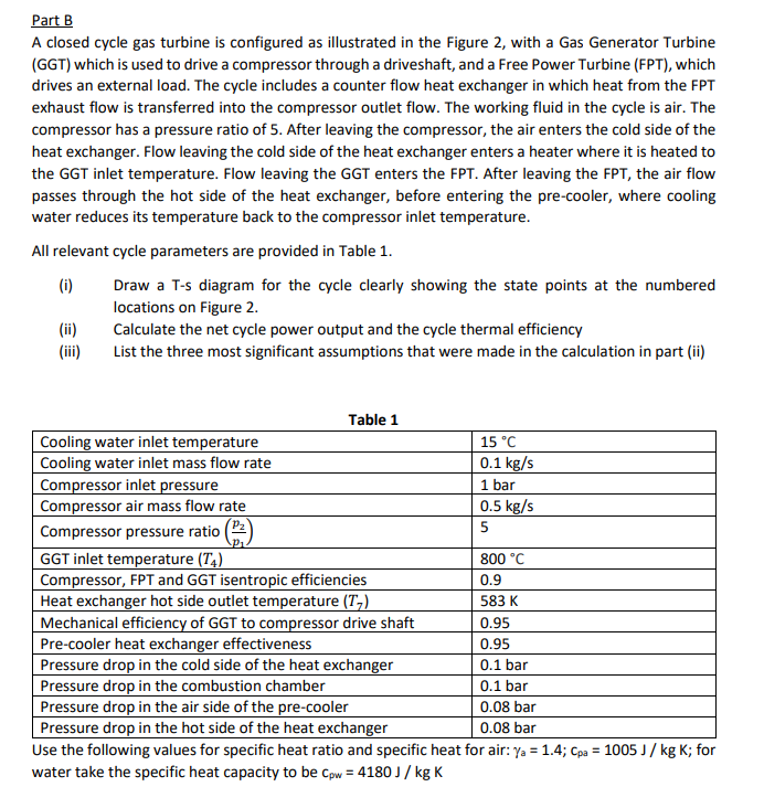
Part B A closed cycle gas turbine is configured as illustrated in the Figure 2, with a Gas Generator Turbine (GGT) which is used to drive a compressor through a driveshaft, and a Free Power Turbine (FPT), which drives an external load. The cycle includes a counter flow heat exchanger in which heat from the FPT exhaust flow is transferred into the compressor outlet flow. The working fluid in the cycle is air. The compressor has a pressure ratio of 5. After leaving the compressor, the air enters the cold side of the heat exchanger. Flow leaving the cold side of the heat exchanger enters a heater where it is heated to the GGT inlet temperature. Flow leaving the GGT enters the FPT. After leaving the FPT, the air flow passes through the hot side of the heat exchanger, before entering the pre-cooler, where cooling water reduces its temperature back to the compressor inlet temperature. All relevant cycle parameters are provided in Table 1. (i) Draw a T-s diagram for the cycle clearly showing the state points at the numbered locations on Figure 2. Calculate the net cycle power output and the cycle thermal efficiency (iii) List the three most significant assumptions that were made in the calculation in part (ii) Table 1 Cooling water inlet temperature 15 °C Cooling water inlet mass flow rate 0.1 kg/s Compressor inlet pressure 1 bar Compressor air mass flow rate 0.5 kg/s Compressor pressure ratio 5 GGT inlet temperature (T4) 800 °C Compressor, FPT and GGT isentropic efficiencies 0.9 Heat exchanger hot side outlet temperature (T) 583 K Mechanical efficiency of GGT to compressor drive shaft 0.95 Pre-cooler heat exchanger effectiveness 0.95 Pressure drop in the cold side of the heat exchanger 0.1 bar Pressure drop in the combustion chamber 0.1 bar Pressure drop in the air side of the pre-cooler 0.08 bar Pressure drop in the hot side of the heat exchanger 0.08 bar Use the following values for specific heat ratio and specific heat for air: Ya = 1.4; Cpa = 1005 / kg K; for water take the specific heat capacity to be Cpw = 4180J / kg K