Home /
Expert Answers /
Electrical Engineering /
for-the-circuit-shown-below-assume-we-have-variable-resistor-r-l-and-variable-capacitor-pa406
(Solved): For the circuit shown below, assume we have variable resistor \( R_{L} \) and variable capacitor \( ...
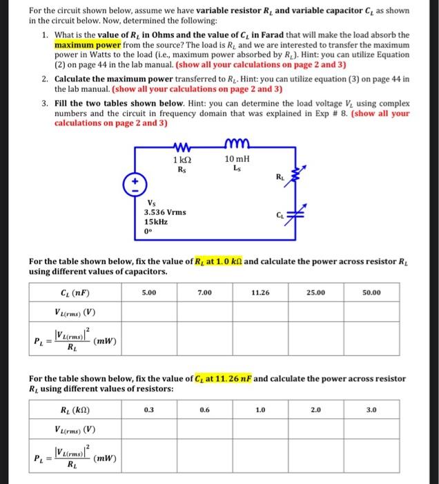
For the circuit shown below, assume we have variable resistor \( R_{L} \) and variable capacitor \( C_{L} \) as shown in the circuit below. Now, determined the following: 1. What is the value of \( R_{L} \) in Ohms and the value of \( C_{L} \) in Farad that will make the load absorb the maximum power from the source? The load is \( R_{L} \) and we are interested to transfer the maximum power in Watts to the load (i.e., maximum power absorbed by \( R_{L} \) ). Hint: you can utilize Equation (2) on page 44 in the lab manual. (show all your calculations on page 2 and 3 ) 2. Calculate the maximum power transferred to \( R_{L} \). Hint: you can utilize equation (3) on page 44 in the lab manual. (show all your calculations on page 2 and 3 ) 3. Fill the two tables shown below. Hint: you can determine the load voltage \( V_{L} \) using complex numbers and the circuit in frequency domain that was explained in Exp \# 8. (show all your calculations on page 2 and 3 ) For the table shown below, fix the value of \( R_{L} \) at \( 1.0 \mathrm{k} \Omega \) and calculate the power across resistor \( R_{L} \) using different values of capacitors. For the table shown below, fix the value of \( C_{L} \) at 11. \( 26 n F \) and calculate the power across resistor \( R_{L} \) using different values of resistors:
Expert Answer
1. Maximum power transfer theorem states that if, (1) Z_{L} =Z S ^ * then maximum power will be transferred to Z_{L} but only when Z_{L} is variable.