Home /
Expert Answers /
Electrical Engineering /
for-a-3-phase-power-system-as-shown-in-figure-2-below-it-supplies-a-load-of-30mw-at-132kv-0-85-pow-pa973
(Solved): For a 3-phase power system as shown in Figure 2 below, it supplies a load of 30MW at 132kV,0.85 pow ...
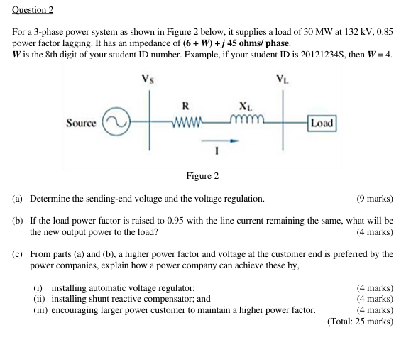
For a 3-phase power system as shown in Figure 2 below, it supplies a load of at power factor lagging. It has an impedance of phase. is the 8th digit of your student ID number. Example, if your student ID is , then . (a) Determine the sending-end voltage and the voltage regulation. marks) (b) If the load power factor is raised to 0.95 with the line current remaining the same, what will be the new output power to the load? (4 marks) (c) From parts (a) and (b), a higher power factor and voltage at the customer end is preferred by the power companies, explain how a power company can achieve these by, (i) installing automatic voltage regulator; (ii) installing shunt reactive compensator; and (iii) encouraging larger power customer to maintain a higher power factor. (4 marks) (4 marks) (4 marks) (Total: 25 marks)
Expert Answer
To determine the sending-end voltage and the voltage regulation, we need to calculate the line current, sending-end voltage, and the load voltage. Given information: Load power (P) = 30 MW Voltage (V) = 132 kV Power factor (PF) = 0.85 lagging Impedance (Z) = (6 + W) + j45 ohms/phasea):-current I=Pr?3Vrcos?Vr=132kV , Pr=30MWI=Pr?3Vrcos?=30?106?3132?103?0.85=154.371Ain polar form I=154.371??cos?1(0.85)=154.371??31.788?sending end voltageVs=Vr+ZI=132?103?3+(10+j45)(154.371??31.788Vs=81.341?103?3.5888? V