Home /
Expert Answers /
Electrical Engineering /
figure-p12-8-12-8-the-60-mile-115-mathrm-kv-line-gh-figure-p12-8-i-pa424
(Solved): FIGURE P12.8 12.8 The 60 mile, \( 115 \mathrm{kV} \) line GH (Figure P12.8) i ...
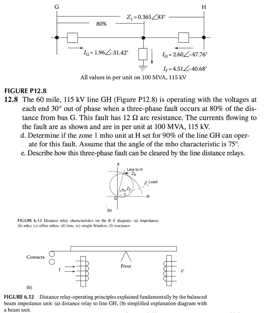
FIGURE P12.8 12.8 The 60 mile, \( 115 \mathrm{kV} \) line GH (Figure P12.8) is operating with the voltages at each end \( 30^{\circ} \) out of phase when a three-phase fault occurs at \( 80 \% \) of the distance from bus \( \mathrm{G} \). This fault has \( 12 \Omega \) arc resistance. The currents flowing to the fault are as shown and are in per unit at \( 100 \mathrm{MVA}, 115 \mathrm{kV} \). d. Determine if the zone 1 mho unit at \( \mathrm{H} \) set for \( 90 \% \) of the line \( \mathrm{GH} \) can operate for this fault. Assume that the angle of the mho characteristic is \( 75^{\circ} \). e. Describe how this three-phase fault can be cleared by the line distance relays. FIGURE 6.13 Distance relay characteristics on the \( R-X \) diagram: (a) impedance; (b) mho; (c) offset mhos; (d) lens; (e) simple blinders; (f) reactance. FIGURE 6.12 Distance relay-operating principles explained fundamentally by the balanced beam impedance unit: (a) distance relay to line \( \mathrm{GH} \), (b) simplified explanation diagram with a beam unit.