Home /
Expert Answers /
Electrical Engineering /
figure-6-an-active-rc-differentiator-c-1f-implement-the-differentiator-given-in-the-schematic-pa452
(Solved): Figure 6: An active RC differentiator (C=1F) Implement the differentiator given in the schematic ...
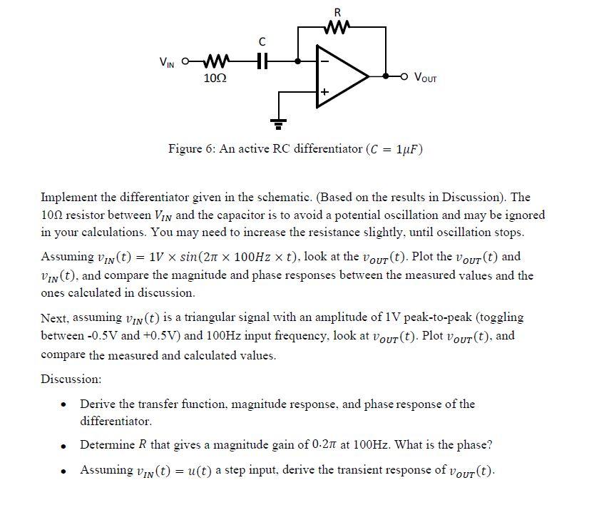
Figure 6: An active differentiator Implement the differentiator given in the schematic. (Based on the results in Discussion). The resistor between and the capacitor is to avoid a potential oscillation and may be ignored in your calculations. You may need to increase the resistance slightly, until oscillation stops. Assuming , look at the . Plot the and , and compare the magnitude and phase responses between the measured values and the ones calculated in discussion. Next, assuming is a triangular signal with an amplitude of peak-to-peak (toggling between and and input frequency, look at . Plot , and compare the measured and calculated values. Discussion: - Derive the transfer function, magnitude response, and phase response of the differentiator. - Determine that gives a magnitude gain of at . What is the phase? - Assuming a step input, derive the transient response of .