Home /
Expert Answers /
Electrical Engineering /
figure-4-shows-a-jfet-in-the-source-follower-configuration-with-the-following-parameters-v-g-pa498
(Solved): Figure 4 shows a JFET in the source-follower configuration with the following parameters: \( V_{G ...
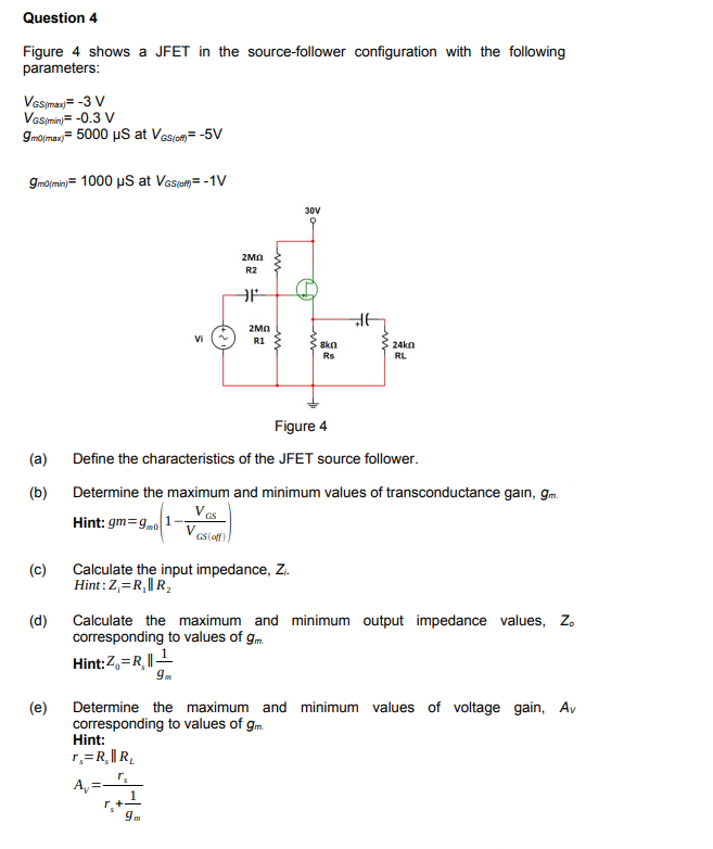
Figure 4 shows a JFET in the source-follower configuration with the following parameters: \( V_{G S(\max )}=-3 \mathrm{~V} \) \( V_{G S(\min )}=-0.3 \mathrm{~V} \) \( g_{\operatorname{mo(max})}=5000 \mu \mathrm{S} \) at \( V_{G S(\mathrm{amin})}=-5 \mathrm{~V} \) \( g_{m 0(\text { min })}=1000 \mu S \) at \( V_{G S(o f f)}=-1 \mathrm{~V} \) (a) Define the characteristics of the JFET source follower. (b) Determine the maximum and minimum values of transconductance ga?n, \( g_{\mathrm{m}} \). Hint: \( g m=g_{m 0}\left(1-\frac{V_{G S}}{V_{C S(\text { off }}}\right) \) (c) Calculate the input impedance, \( Z_{i} \). Hint: \( Z_{i}=R_{1} \| R_{2} \) (d) Calculate the maximum and minimum output impedance values, \( Z_{\text {o }} \) corresponding to values of \( g_{m} \). Hint: \( Z_{0}=R_{s} \| \frac{1}{g_{m}} \) (e) Determine the maximum and minimum values of voltage gain, \( A_{V} \) corresponding to values of \( g_{m} \). Hint: \[ \begin{array}{l} r_{s}=R_{s} \| R_{L} \\ A_{V}=\frac{r_{s}}{r_{s}+\frac{1}{g_{m}}} \end{array} \]