Home /
Expert Answers /
Mechanical Engineering /
figure-3-level-venturi-tube-connected-to-u-tube-manometer-q-3-a-starting-from-bernoulli-39-s-equati-pa514
(Solved): Figure 3: Level Venturi Tube connected to U-tube manometer. Q 3(a) Starting from Bernoulli's equati ...
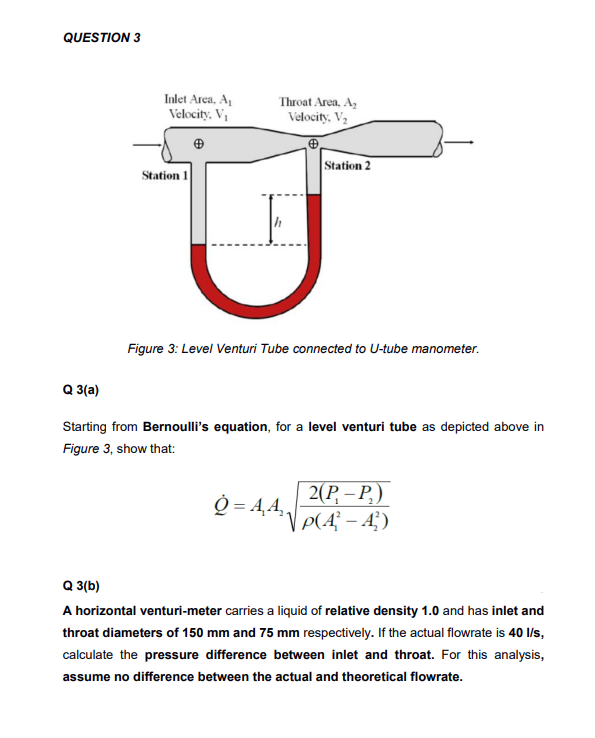
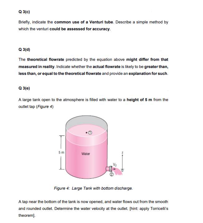
Figure 3: Level Venturi Tube connected to U-tube manometer. Q 3(a) Starting from Bernoulli's equation, for a level venturi tube as depicted above in Figure 3, show that: Q 3(b) A horizontal venturi-meter carries a liquid of relative density 1.0 and has inlet and throat diameters of and respectively. If the actual flowrate is , calculate the pressure difference between inlet and throat. For this analysis, assume no difference between the actual and theoretical flowrate.
Q 3(c) Briefly, indicate the common use of a Venturi tube. Describe a simple method by which the venturi could be assessed for accuracy. Q 3(d) The theoretical flowrate predicted by the equation above might differ from that measured in reality. Indicate whether the actual flowrate is likely to be greater than, less than, or equal to the theoretical flowrate and provide an explanation for such. Q 3(e) A large tank open to the atmosphere is filled with water to a height of from the outlet tap (Figure 4) Figure 4: Large Tank with bottom discharge. A tap near the bottom of the tank is now opened, and water flows out from the smooth and rounded outlet. Determine the water velocity at the outlet. [hint: apply Torricelli's theorem].
Expert Answer
The continuity equation for incompressible fluids gives us The elevation of the two points on the Ve...