Home /
Expert Answers /
Electrical Engineering /
figure-21-2-simplified-diagram-of-a-homodyne-recerver-configuration-estimate-the-bandpass-filt-pa647
(Solved): Figure 21.2. Simplified diagram of a homodyne recerver configuration. Estimate the bandpass filt ...


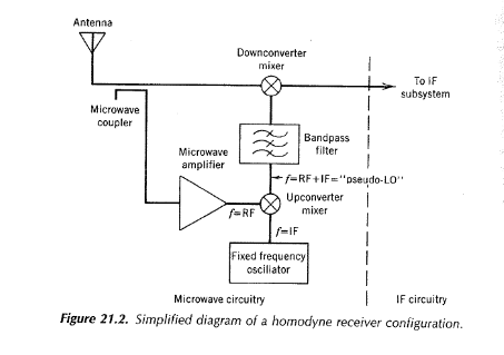
Figure 21.2. Simplified diagram of a homodyne recerver configuration.
Estimate the bandpass filter rejection required between the two mixers in the homodyne receiver to avoid the "image." The microwave amplifier in Fig. 21.2 must have what characteristic to allow the receiver to have wide dynamic range?